A maintenance device for interlayer insulators of flexible straight valve towers
A technology for interlayer insulation and maintenance devices, which is applied to switchgear, electrical components, etc., can solve problems such as large lateral or side loads, valve tower damage, etc., and achieve high safety, effective maintenance, and low cost effects
- Summary
- Abstract
- Description
- Claims
- Application Information
AI Technical Summary
Problems solved by technology
Method used
Image
Examples
Embodiment 1
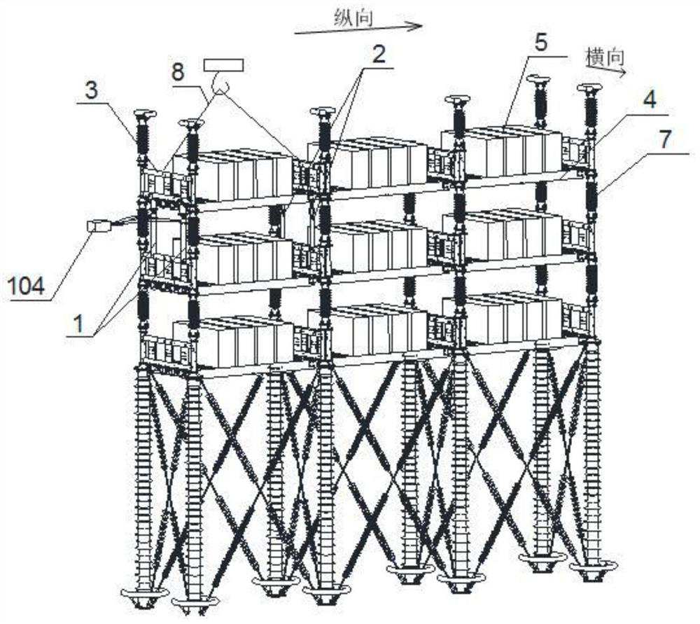
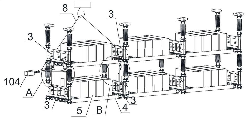
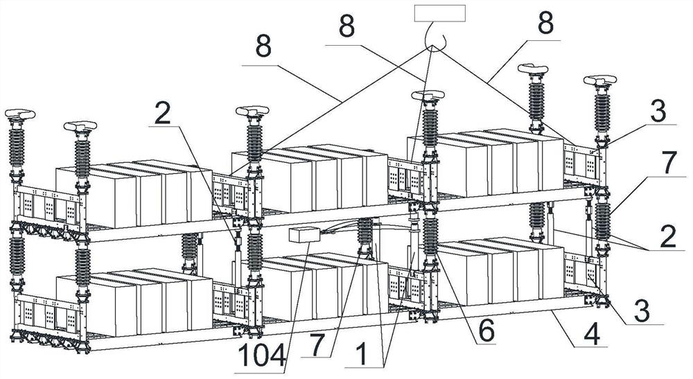
[0046] Example 1, such as figure 1 As shown, a flexible straight valve tower interlayer insulator inspection device is used for a valve tower structure with three layers of valve towers, and each layer has three modules 5 arranged in series, and each module 5 is placed in a On the insulating beam 4, the longitudinal sides of the insulating beam 4 are respectively connected with a valve section frame 3 by bolts, and the bolts are installed along the horizontal direction. When the valve section frame 3 moves up and down, the insulating beam 4 and the valve section frame 3 can produce a certain relative rotation , to prevent the insulating beam 4 from twisting, and the upper and lower valve section frames 3 are connected by interlayer insulators 7, such as figure 2 , image 3 As shown, the insulator replacement unit in this embodiment includes two sets of telescopic assemblies 1, and the plane of the two sets of telescopic assemblies 1 is parallel to the plane of the valve sect...
Embodiment 2
[0052] Embodiment 2, when the fixed assembly 2 is installed, first rotate the adjusting screw 203 to shorten the fixed assembly 2 until the fixed assembly 2 can be placed between the upper and lower valve section frames 3, and the upper and lower ends of the fixed assembly 2 and the upper and lower valve section frames 3 After fixing, rotate the adjusting screw 203 to make the upper and lower valve section frames 3 tense, and the upper and lower valve section frames 3 are slightly stressed, so it is necessary to use a large force to rotate the adjusting screw 203. In order to facilitate the operation with tools, such as Image 6 As shown, the adjusting screw 203 in this embodiment includes an intermediate fastening section 2032 and a threaded section 2031 connecting the two ends of the intermediate fastening section 2032. The two threaded sections 2031 are threadedly connected with the upper pull rod 201 and the lower pull rod 202 respectively, and the middle fastening The sect...
Embodiment 3
[0053] Embodiment 3, embodiment 1 or embodiment 2, the jack 103 can be directly between the upper block 101 and the lower block 102, but if the jack 103 is placed tilted or subjected to external force, the jack 103 will be very slow in the process of jacking up. Rollover is prone to occur, causing the valve section frame 3 to tilt instantly and the interlayer insulator 7 to be damaged. Therefore, in this embodiment, circular grooves 105 are provided on the connecting end faces of the lower block 102, the upper block 101 and the jack 103, A pin hole is provided in the circular groove 105, such as Figure 7 As shown, the two ends of the jack 103 are sunken in the circular groove 105 during installation, and the end of the jack 103 is usually sunken inward, and the pin 106 is inserted into the hole of the pin 106 and abuts against the end face of the jack 103, so as to limit the relative Lateral displacement of the upper block 101 or the lower block 102 .
PUM
 Abstract
Description
Claims
Application Information
 - R&D
- Intellectual Property
- Life Sciences
- Materials
- Tech Scout
- Unparalleled Data Quality
- Higher Quality Content
- 60% Fewer Hallucinations
Browse by: Latest US Patents, China's latest patents, Technical Efficacy Thesaurus, Application Domain, Technology Topic, Popular Technical Reports.
© 2025 PatSnap. All rights reserved.Legal|Privacy policy|Modern Slavery Act Transparency Statement|Sitemap|About US| Contact US: help@patsnap.com


