Workpiece safety intelligent polishing machine

A polishing machine and safety technology, applied in the field of polishing machines, can solve the problems of resource waste, polishing efficiency and low safety, and achieve the effect of increasing safety

Active Publication Date: 2019-09-24
山东劳耐驰汽车有限公司
View PDF4 Cites 3 Cited by
  • Summary
  • Abstract
  • Description
  • Claims
  • Application Information

AI Technical Summary

Problems solved by technology

[0003] In order to overcome the disadvantages of low polishing efficiency and safety in existing mechanical polishing methods, which are likely to cause large waste of resources, the purpose of the present invention is to provide a workpiece safety device with high polishing efficiency and safety, which is not easy to cause waste of resources. Intelligent polishing machine

Method used


Image

  • Workpiece safety intelligent polishing machine
  • Workpiece safety intelligent polishing machine
  • Workpiece safety intelligent polishing machine

Examples


Embodiment 1

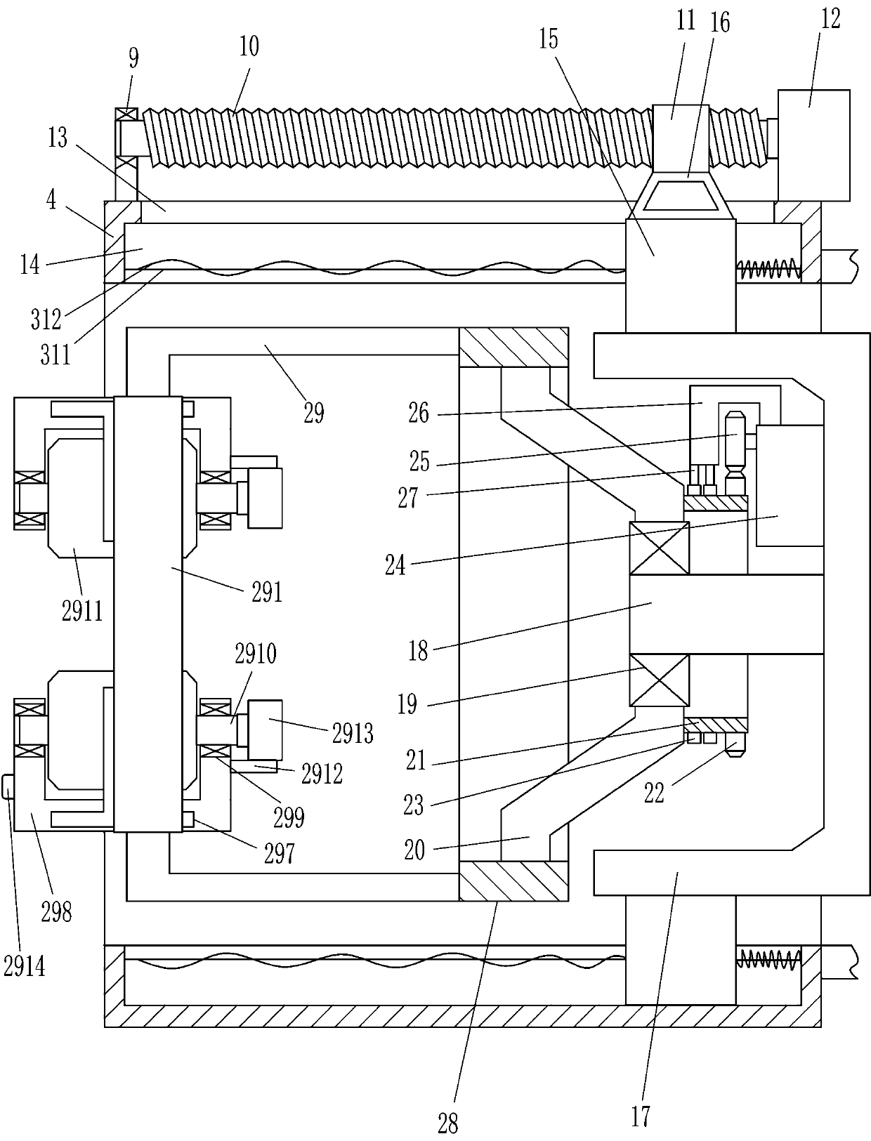
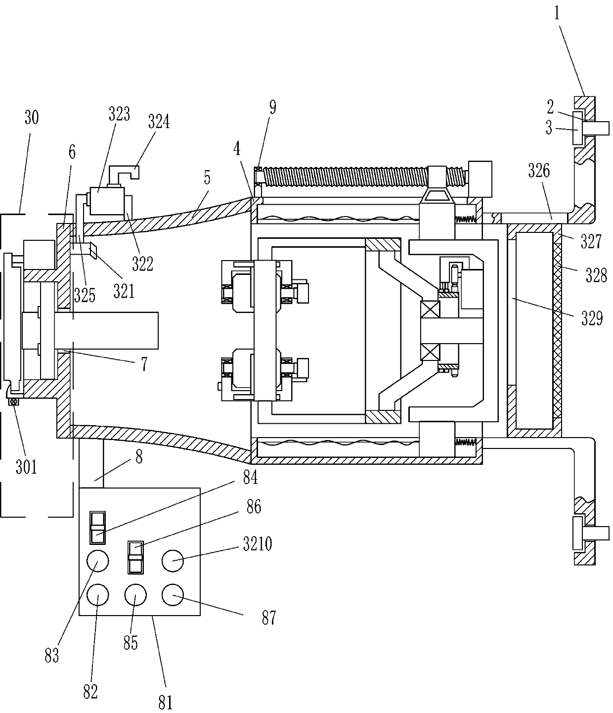
[0020] A workpiece safety intelligent polishing machine, such as Figure 1-7As shown, it includes installation frame 1, expansion screw 3, installation box 4, operation box 5, observation glass 51, fixed frame 6, first connection block 8, control box 81, main power switch 82, second switch 83, the first A ship type switch 84, the third switch 85, the second ship type switch 86, the fourth switch 87, the first bearing block 9, the first screw mandrel 10, the first nut 11, the reduction motor 12, the slide rail 14, the slide block 15, The second connecting block 16, the first N-shaped frame 17, the fixed rod 18, the second bearing seat 19, the first connecting frame 20, the first rotating ring 21, the first gear 22, the receiving ring 23, and the first driving motor 24 , second gear 25, second connecting frame 26, electrode 27, second rotating ring 28, third connecting frame 29, second N-shaped frame 291, first guide rail 292, first guide sleeve 293, third bearing seat 294 , th...

Embodiment 2

[0022] A workpiece safety intelligent polishing machine, such as Figure 1-7 As shown, it includes installation frame 1, expansion screw 3, installation box 4, operation box 5, observation glass 51, fixed frame 6, first connection block 8, control box 81, main power switch 82, second switch 83, the first A ship type switch 84, the third switch 85, the second ship type switch 86, the fourth switch 87, the first bearing block 9, the first screw mandrel 10, the first nut 11, the reduction motor 12, the slide rail 14, the slide block 15, The second connecting block 16, the first N-shaped frame 17, the fixed rod 18, the second bearing seat 19, the first connecting frame 20, the first rotating ring 21, the first gear 22, the receiving ring 23, and the first driving motor 24 , second gear 25, second connecting frame 26, electrode 27, second rotating ring 28, third connecting frame 29, second N-shaped frame 291, first guide rail 292, first guide sleeve 293, third bearing seat 294 , t...

Embodiment 3

[0025] A workpiece safety intelligent polishing machine, such as Figure 1-7As shown, it includes installation frame 1, expansion screw 3, installation box 4, operation box 5, observation glass 51, fixed frame 6, first connection block 8, control box 81, main power switch 82, second switch 83, the first A ship type switch 84, the third switch 85, the second ship type switch 86, the fourth switch 87, the first bearing block 9, the first screw mandrel 10, the first nut 11, the reduction motor 12, the slide rail 14, the slide block 15, The second connecting block 16, the first N-shaped frame 17, the fixed rod 18, the second bearing seat 19, the first connecting frame 20, the first rotating ring 21, the first gear 22, the receiving ring 23, and the first driving motor 24 , second gear 25, second connecting frame 26, electrode 27, second rotating ring 28, third connecting frame 29, second N-shaped frame 291, first guide rail 292, first guide sleeve 293, third bearing seat 294 , th...


PUM


Abstract

The invention relates to a polishing machine, in particular to a workpiece safety intelligent polishing machine. The invention aims to provide the workpiece safety intelligent polishing machine which is high in polishing efficiency and safety and not prone to cause resource waste. The workpiece safety intelligent polishing machine comprises mounting frames, expansion screws, a mounting box, an operation box, an observation glass, a fixing frame, a first connecting block, a control box, a power supply main switch, a second switch and the like, wherein the mounting frames are both arranged on the upper portion and the lower portion of the right side face of the mounting box correspondingly, mounting holes are both formed in the mounting frames, the expansion screws are both arranged in the mounting holes in a penetrating mode, and the expansion screws are fixed on a wall. According to the polishing machine, the dustproof cloth can block a corss-shaped hole to form a closed environment, so that scrap iron generated during polishing is prevented from being splashed out through the corss-shaped hole, and then the safety of the device is improved, and a worker can press a first rocker switch to different gears, so that the distance between an upper clamping block and a lower clamping block is increased or decreased, and then workpieces with different thickness degrees can be clamped.

Description

technical field [0001] The invention relates to a polishing machine, in particular to a workpiece safety intelligent polishing machine. Background technique [0002] In the process of industrial production, in order to reduce the roughness of the workpiece surface and make the surface of the workpiece brighter and smoother, the workpiece needs to be polished. Now the method of mechanical polishing is generally used. Mechanical polishing generally uses oil stone strips, wool wheels, sandpaper, etc. Mainly manual operation, when polishing, the staff puts the rough workpiece on the rotary table for polishing. Utilize this method to carry out polishing speed slower, thereby can influence working efficiency; And the iron filings that produce in polishing process easily splashes on the body of the worker, and safety is lower; The materials for polishing are extremely easy to wear and tear, which is likely to cause a large waste of resources. Contents of the invention [0003] ...

Claims


Application Information

Patent Timeline
Patent Type & Authority Applications(China)
IPC IPC(8): B24B41/06B24B55/06B24B55/00B24B27/00B24B29/00B24B47/12
CPCB24B27/0015B24B27/0076B24B29/00B24B41/06B24B47/12B24B55/00B24B55/06
Inventor 琚梦瑶
Owner 山东劳耐驰汽车有限公司
Why Eureka
Try Eureka