
Lamp trough structure device of ceiling and mounting method of lamp trough structure device

A lamp trough and ceiling technology, applied in lighting devices, household cleaning devices, lighting auxiliary devices, etc., can solve the problems of inconvenient cleaning of lamp troughs, obstructing the head, inconvenient maintenance and replacement of lamp tubes, etc., and achieve better decoration effect and convenience. The effect of installation and convenient operation

Active Publication Date: 2019-09-24
上海紫尧实业有限公司
View PDF5 Cites 2 Cited by
  • Summary
  • Abstract
  • Description
  • Claims
  • Application Information

AI Technical Summary

Problems solved by technology

But the ceiling light trough device in the above-mentioned patent also has the following disadvantages when in use, the first; because the light tube is installed in the light trough, therefore, the maintenance and replacement of the light tube after damage is inconvenient, and, The height of the light trough is small and the top of the light trough is at the same height as the top of the house, which will hinder the head and make it impossible to see the environment inside the light trough at the eye level, which increases the difficulty of disassembly and maintenance of the lamp
Second, the air contains dust. Therefore, after a long time, the light trough is bound to be covered with dust, and the inside of the light trough is full of lamps and lines, which will bring inconvenience to the cleaning of the light trough.

Method used

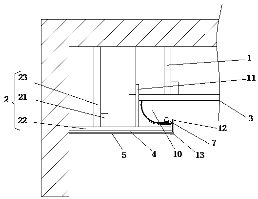
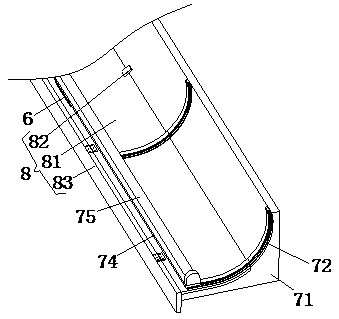
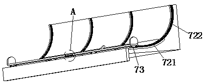

Image

  • Lamp trough structure device of ceiling and mounting method of lamp trough structure device
  • Lamp trough structure device of ceiling and mounting method of lamp trough structure device
  • Lamp trough structure device of ceiling and mounting method of lamp trough structure device

Examples


Embodiment Construction

[0024] In order to make the object, technical solution and advantages of the present invention more clear, the present invention will be further described in detail below in conjunction with the accompanying drawings and embodiments. It should be understood that the specific embodiments described here are only used to explain the present invention, not to limit the present invention.

[0025] In describing the present invention, it should be understood that the terms "longitudinal", "transverse", "upper", "lower", "front", "rear", "left", "right", "vertical", The orientations or positional relationships indicated by "horizontal", "top", "bottom", "inner", "outer", etc. are based on the orientations or positional relationships shown in the drawings, and are only for the convenience of describing the present invention, rather than indicating or It should not be construed as limiting the invention by implying that a referenced device or element must have a particular orientation,...


PUM


Abstract

The invention relates to the technical field of indoor decoration, in particular to a lamp trough structure device of a ceiling. The lamp trough structure device comprises a first fixing frame and a second fixing frame, the second fixing frame is mounted at the edge of the indoor top and mounted in the middle of the first fixing frame, a first face decorating plate is arranged at the lower end of the first fixing frame, a connecting plate is arranged at the lower end of the second fixing frame, a second face decorating plate is arranged at the lower end of the connecting plate, a fixing plate used for connecting the first fixing frame with the second fixing frame is arranged between the first fixing frame and the second fixing frame, a lamp trough is formed among the first face decorating plate, the second face decorating plate and the fixing plate and internally provided with an adjusting assembly, a turning-over assembly and a sweeping assembly, and the turning-over assembly and the sweeping assembly are both mounted on the adjusting assembly. Through arrangement of the adjusting assembly, the turning-over assembly and the sweeping assembly, the effects of adjusting light, conveniently maintaining and replacing a lamp strip and conveniently clearing dust inside the lamp trough can be realized.

Description

technical field [0001] The invention relates to the technical field of interior decoration, in particular to a ceiling lamp trough structure device and an installation method thereof. Background technique [0002] The ceiling light trough is the core element of the ceiling. The ceiling light trough uses hidden lamps to create an environment with diffused light, rendering a unique light and shadow environment in the space of "seeing the light but not the light". [0003] Chinese Patent No. CN201610082185.4 discloses a ceiling lamp trough device and an installation method, the ceiling lamp trough device includes: a top joist and a bottom joist fixed on the top surface of the room; a top decoration fixed on the top joist a board; a bottom decorative plate fixed on the bottom keel; a plurality of reflective plates arranged between the top keel and the bottom keel. The installation method includes: a keel installation step, a top surface installation step, a bottom surface insta...

Claims


Application Information

Patent Timeline
Patent Type & Authority Applications(China)
IPC IPC(8): E04B9/00E04B9/06E04B9/30F21V21/04F21V19/02A47L25/12
CPCA47L25/12E04B9/00E04B9/006E04B9/06E04B9/30F21V19/02F21V21/047
Inventor 陆静华朱怀军黄世杰王骏
Owner 上海紫尧实业有限公司
Learn More