Self-locking cantilever beam, bearing device and operation platform

A bearing device and operating platform technology, applied in the direction of building structure support, building structure support, building structure support scaffolding, etc., can solve the problems of difficulty and risk of installation or disassembly, achieve convenient disassembly, improve stability, and enhance stability sexual effect

Pending Publication Date: 2019-09-24
广州中石科技有限公司 +1
View PDF0 Cites 4 Cited by
  • Summary
  • Abstract
  • Description
  • Claims
  • Application Information

AI Technical Summary

Problems solved by technology

[0003] No matter what kind of scaffolding platform is used, a large amount of scaffolding materials are required, and professional personnel are required to

Method used


Image

  • Self-locking cantilever beam, bearing device and operation platform
  • Self-locking cantilever beam, bearing device and operation platform
  • Self-locking cantilever beam, bearing device and operation platform

Examples


Embodiment 1

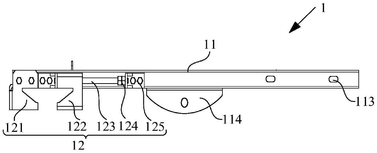
[0043]The application provides a self-locking cantilever beam, including a beam and a clamping assembly arranged at one end of the beam; the clamping assembly includes a first clamping piece, a second clamping piece, a connecting rod and a locking piece, the first The clamping part is arranged at one end of the beam, the two ends of the connecting rod are connected to the beam, and the second clamping part is passed through the connecting rod; the second clamping part can move toward or away from the first clamping part, so that at the A clamping space whose range can be adjusted is formed between the first clamping part and the second clamping part; when the second clamping part moves to a predetermined position, the locking part can lock and limit the displacement of the second clamping part.

[0044] Wherein, it should be noted that the locking of the locking member and restricting the displacement of the second clamping member may include, for example, two situations. The f...

Embodiment 2

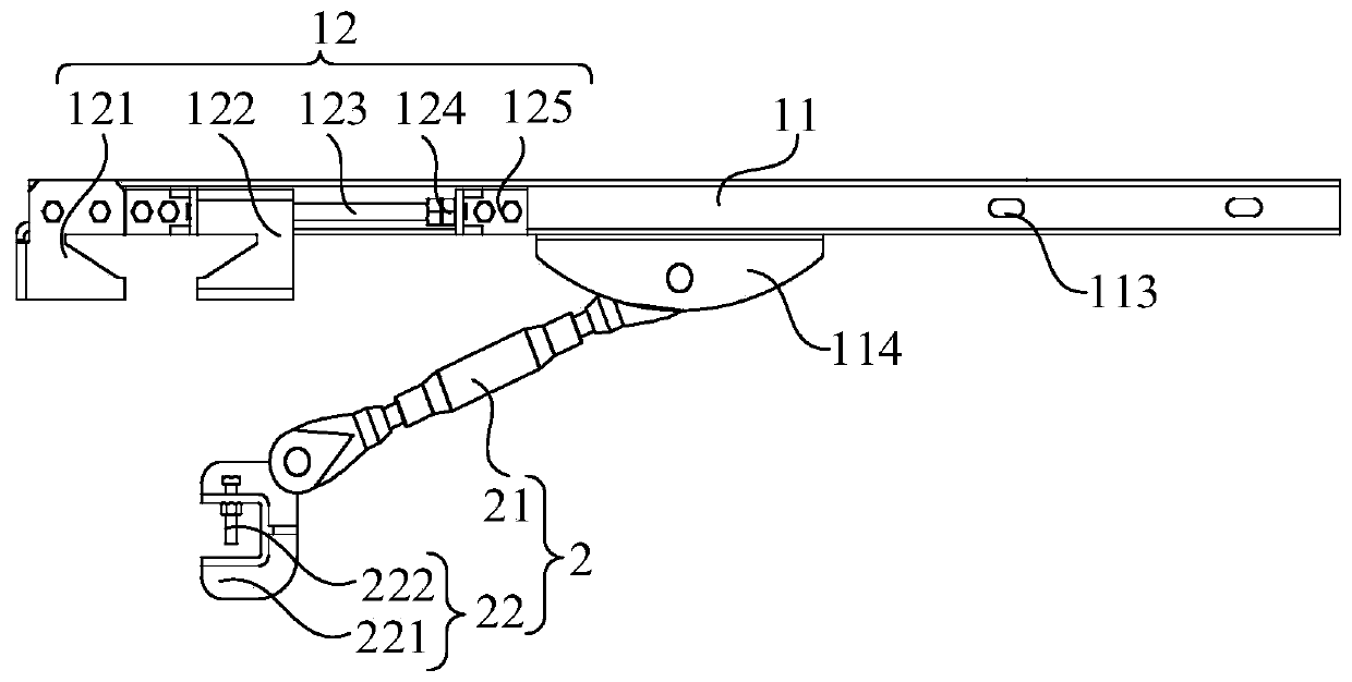
[0053] Such as Figure 1 to Figure 5 As shown, the embodiment of the present application provides a carrying device, including the support 2 and the self-locking cantilever beam 1 in the first embodiment; since the self-locking cantilever beam 1 has the technical effect in the first embodiment, so The carrying device with the self-locking cantilever beam 1 also has the same technical effect, and further the same structural features will not be repeated one by one.

[0054] The support member 2 includes a telescopic rod 21 and a third clamping member 22 , one end of the telescopic rod 21 is hinged to the center of the lower abdomen of the beam 11 , and the other end is hinged to the third clamping member 22 .

[0055] Such as image 3 As shown, one end of the telescopic rod 21 is hinged to the mount 114 on the beam 11 , and the other end is hinged to the third clamping member 22 , which is used to clamp other components.

[0056] The structure of telescopic rod 21 is as Fig...

Embodiment 3

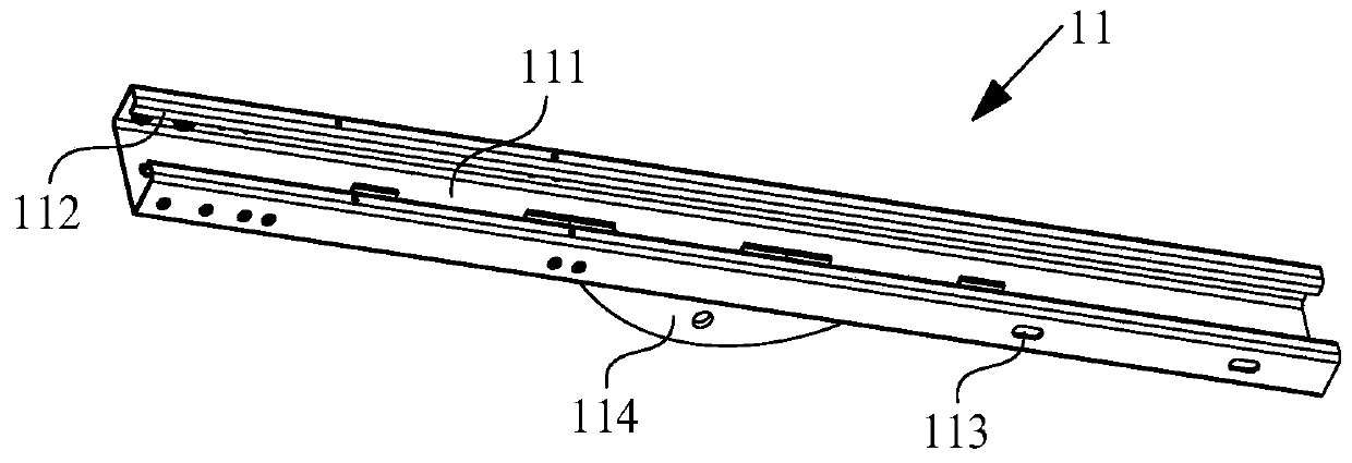
[0060] Such as Figure 1 to Figure 8 As shown, the embodiment of the present application provides a working platform, including a platform board 3 and at least two carrying devices in the second embodiment. Since the carrying device has the technical effect in the second embodiment, the working platform with the carrying device It also has the same technical effect, and then the same structural features will not be repeated one by one; the bearing devices are arranged at intervals, and the platform board 3 is provided with an anti-detachment hook, which can slide into the long groove 111 of the crossbeam 11 and can be connected with the hem 112 are hooked so that the platform board 3 is installed on every two adjacent carrying devices.

[0061] Such as Figure 6 As shown, the platform board 3 is used for people to walk and stand. The two ends of the platform board 3 have anti-detachment hooks. When installing, the anti-detachment hooks slide into the long groove 111 of the be...


PUM


Abstract

The invention provides a self-locking cantilever beam, a bearing device and an operation platform and relates to the technical field of construction tools. The self-locking cantilever beam comprises a cross beam and a clamping assembly arranged at one end of the cross beam. The clamping assembly can achieve the self-locking function. The clamping assembly comprises a first clamping part, a second clamping part, a connecting rod and a locking part. The first clamping part is arranged at one end of the cross beam. The two ends of the connecting rod are connected to the cross beam. The second clamping part is arranged on the connecting rod in a penetrated mode. The second clamping part can move close to or far away from the first clamping part to form a range adjustable clamping space between the first clamping part and the second clamping part. When the second clamping part moves to a preset position, the locking part can lock and limit displacement of the second clamping part so as to complete mounting of the self-locking cantilever beam. The self-locking cantilever beam is easy and convenient to mount and demount and can reduce the mounting risk of the personnel when personnel work at heights.

Description

technical field [0001] The application relates to the technical field of construction tools, in particular to a self-locking cantilever beam, a carrying device and a working platform. Background technique [0002] Aerial work often adopts the method of setting up scaffolding platforms or passages for construction. In the prior art, cantilevered or floor-standing scaffolding platforms or passages are often used; wherein, the cantilevered scaffolding platform is composed of scaffolding steel pipes and fasteners to form a triangle. The support system is to lay scaffolding boards on it; the floor-standing scaffolding platform is set up on the ground or a rigid structure platform with scaffolding steel pipe fasteners to form a bent frame, and scaffolding boards are laid on it. [0003] No matter what kind of scaffolding platform is used, a large amount of scaffolding materials are required, and professional personnel are required to install it. Since scaffolding operations are ba...

Claims


Application Information

Patent Timeline
IPC IPC(8): E04G3/18E04G5/00
CPCE04G3/18E04G5/00
Inventor 杨继民张化成禄登利郭润华石林峰郁海涛
Owner 广州中石科技有限公司
Why Eureka
Try Eureka