
Intelligent flagpole capable of rotating windward along with wind

A rotary, flagpole technology, applied in program control, instrument, speed/acceleration/impact measurement, etc., can solve the problems of high wind loss, high motor power, large resistance, etc., to avoid flag entanglement, low motor power, The effect of low air loss

Pending Publication Date: 2019-09-24
田明光
View PDF0 Cites 1 Cited by
  • Summary
  • Abstract
  • Description
  • Claims
  • Application Information

AI Technical Summary

Problems solved by technology

However, we have seen that the flag cannot be stretched and fluttered due to the lack of natural wind and other meteorological conditions, especially in the middle and lower parts of the flagpole, the flag is rarely stretched and fluttered; the flag is raised, lowered, or set at a certain height Sometimes, due to the continuous change of the natural wind direction, the flag is often wrapped around the flagpole and cannot be stretched and fluttered unsightly. In the case of no wind or light wind, the flag cannot be stretched and fluttered well. If it occurs during a major event This kind of situation is quite regrettable. Most people feel the same, and they all have a vision for change.
The inventor has developed a flagpole that automatically rotates to make up the wind. Both the rotating motor and the blower motor are installed at the base. The resistance encountered in the rotation is large, the required motor power is large, and the wind loss is high.

Method used


Image

  • Intelligent flagpole capable of rotating windward along with wind
  • Intelligent flagpole capable of rotating windward along with wind
  • Intelligent flagpole capable of rotating windward along with wind

Examples


Embodiment 1

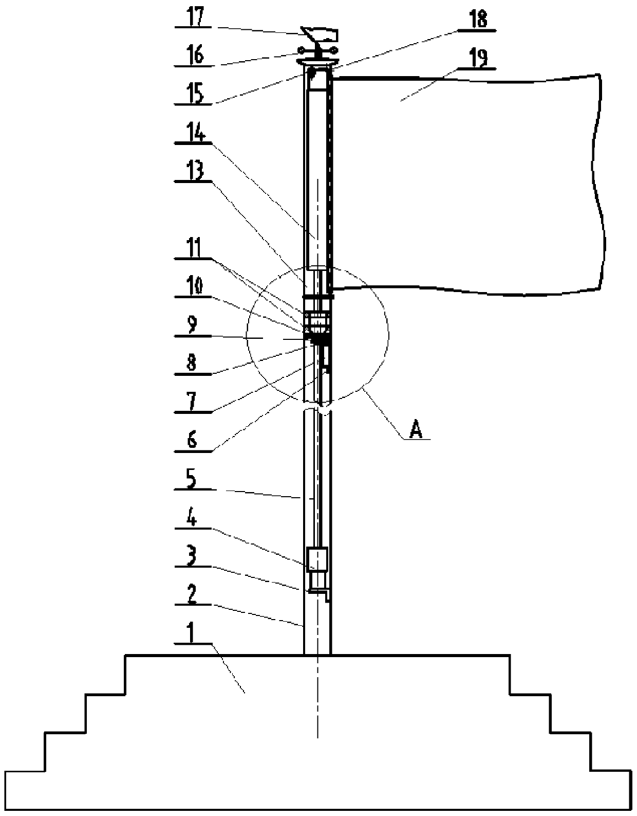
[0021] Embodiment 1: The present invention provides an intelligent flagpole that rotates in the direction of the wind, including a flagpole base 1, and a flagpole body fixed on the flagpole base 1. The flag 19 is raised and lowered by a traction rope and a fixed pulley 18.

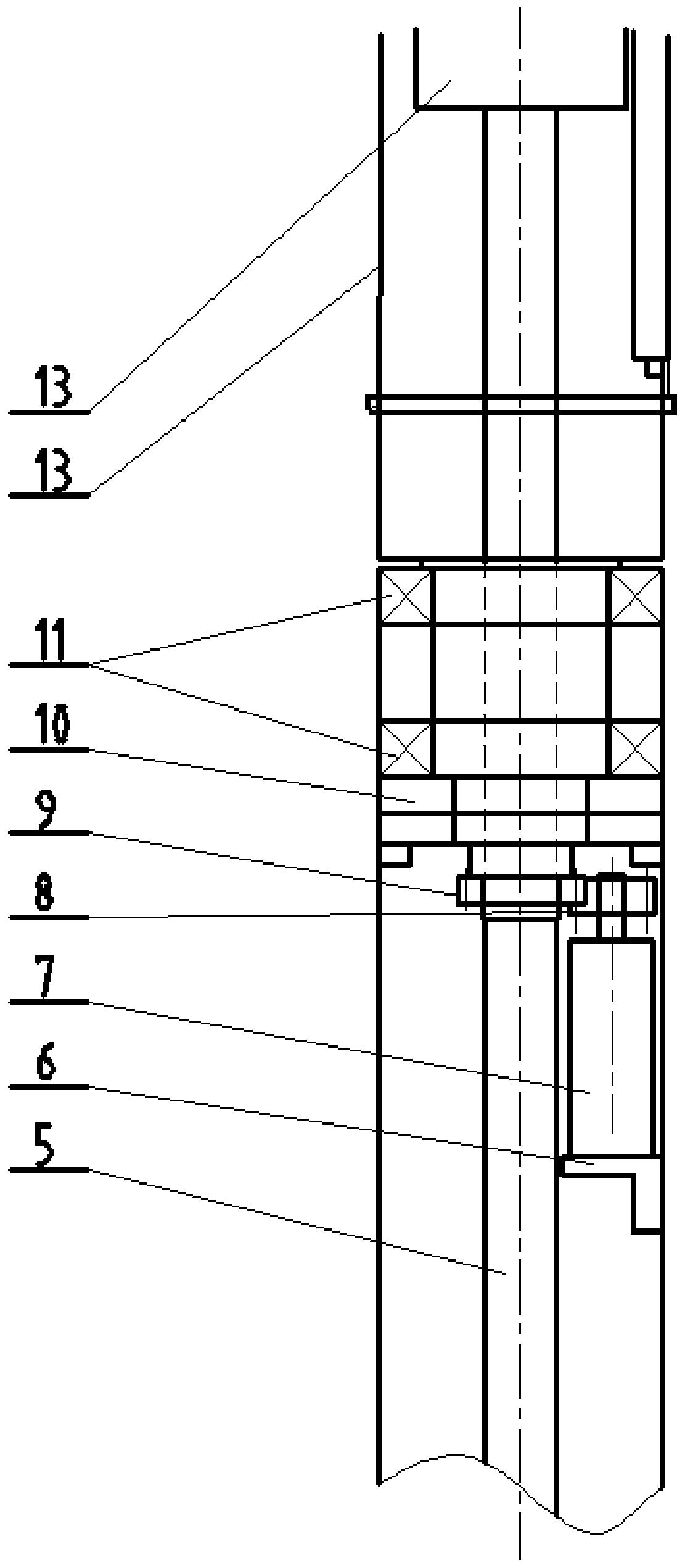
[0022] The flagpole body in this embodiment includes a fixed flagpole 2 and a rotating flagpole 13, and the fixed flagpole 2 and the rotating flagpole 13 are connected by two freely rotatable rotating bearings 11. When the wind speed is relatively large, the rotating flagpole 13 Automatically rotate the angle to keep the flag fluttering in the wind and avoid the entanglement of the traction rope. In case of a power outage, the rotating part of the upper part of the flagpole can also pull the upper part of the flagpole to rotate under the state of natural wind force through the force of the natural wind force on the flag, so that the flag can automatically fly against the wind.

[0023] Simultaneously, in t...


PUM


Abstract

The invention provides an intelligent flagpole capable of rotating windward along with wind. The intelligent flagpole capable of rotating windward along with the wind comprises a flagpole base and a flagpole body. The flagpole body is fixed to the flagpole base and comprises a fixed flagpole and a rotating flagpole. The fixed flagpole and the rotating flagpole are connected through two freely rotatable rotating bearings. A rotating device is arranged at the top of the fixed flagpole and comprises a rotating motor, a flagpole gear and a thrust bearing. The rotating motor is fixed to the inner wall of the top of the fixed flagpole. A rotating shaft gear of the rotating motor is meshed with the flagpole gear. The flagpole gear is fixed to the center of the bottom of the thrust bearing. The top of the thrust bearing is connected with the rotating bearings. If power failure happens to the intelligent flagpole capable of rotating windward along with the wind, under the natural wind power state, rotating parts on the upper portions of the flagpoles can also pull the upper portions of the flagpoles to rotate through acting force applied to a flag by natural wind power, the flag automatically flies along with wind, and the middle upper portions of the flags rotate automatically and are used for air supplementing automatically. The motor power is small, the air discharging loss is low, flag winding is avoided, the adaptability is high, and operation convenience is realized.

Description

technical field [0001] The invention relates to an intelligent flagpole, in particular to an intelligent flagpole that rotates with the wind. Background technique [0002] From ancient times to the present, the flag has always been a symbol of the cohesion and centripetal force of the people. In today's era, peace has become the theme of the development of the times. From countries and departments at all levels, to primary and secondary schools or various large-scale sports games, etc., flag-raising and flag-lowering ceremonies It has become an indispensable content for crowd activities, and the flagpole is an indispensable carrier for the flag to fly. Usually, raising and lowering the flag or maintaining a certain height of the flag can basically be completed. However, we have seen that the flag cannot be stretched and fluttered due to the lack of natural wind and other meteorological conditions, especially in the middle and lower parts of the flagpole, the flag is rarely ...

Claims


Application Information

Patent Timeline
Patent Type & Authority Applications(China)
IPC IPC(8): E04H12/32G01P5/02G05B19/042
CPCE04H12/32G05B19/042G01P5/02
Inventor 田明光
Owner 田明光
Learn More