Pitching and azimuth calibration method for remote optical rotary table based on ground remote sensing image map

A remote sensing image and calibration method technology, which is applied to satellite radio beacon positioning systems, measuring devices, instruments, etc., can solve the problems of judging the actual location of the observation site, inconvenient use, and cumbersome operation by industry users, so as to improve operational efficiency and Ease of use effect

Inactive Publication Date: 2019-09-24
DAQING ANRUIDA TECH DEV CO LTD +1
View PDF6 Cites 6 Cited by
  • Summary
  • Abstract
  • Description
  • Claims
  • Application Information

AI Technical Summary

Problems solved by technology

[0002] In the field of wide-area security monitoring, due to the vastness of the monitored area, complex features, and differences in terrain heights, it is difficult to directly determine the actual location of the observation site based on a single matching value of geographic space distance and pitch value. It is also difficult to quickly guide the servo turntable optical monitoring equipment to the target position, which brings troubles of cumbersome operation and inconvenient use to industry users

Method used


Image

  • Pitching and azimuth calibration method for remote optical rotary table based on ground remote sensing image map
  • Pitching and azimuth calibration method for remote optical rotary table based on ground remote sensing image map
  • Pitching and azimuth calibration method for remote optical rotary table based on ground remote sensing image map

Examples


specific Embodiment approach 1

[0025] A method for calibrating the pitch and azimuth of a remote optical turntable based on a ground remote sensing image map, comprising the following steps:

[0026] Step a, configure the high-definition satellite ground image map of the monitored area;

[0027] Step b, adding the installation position and installation height of the servo turntable optical monitoring equipment to the high-definition satellite ground image map;

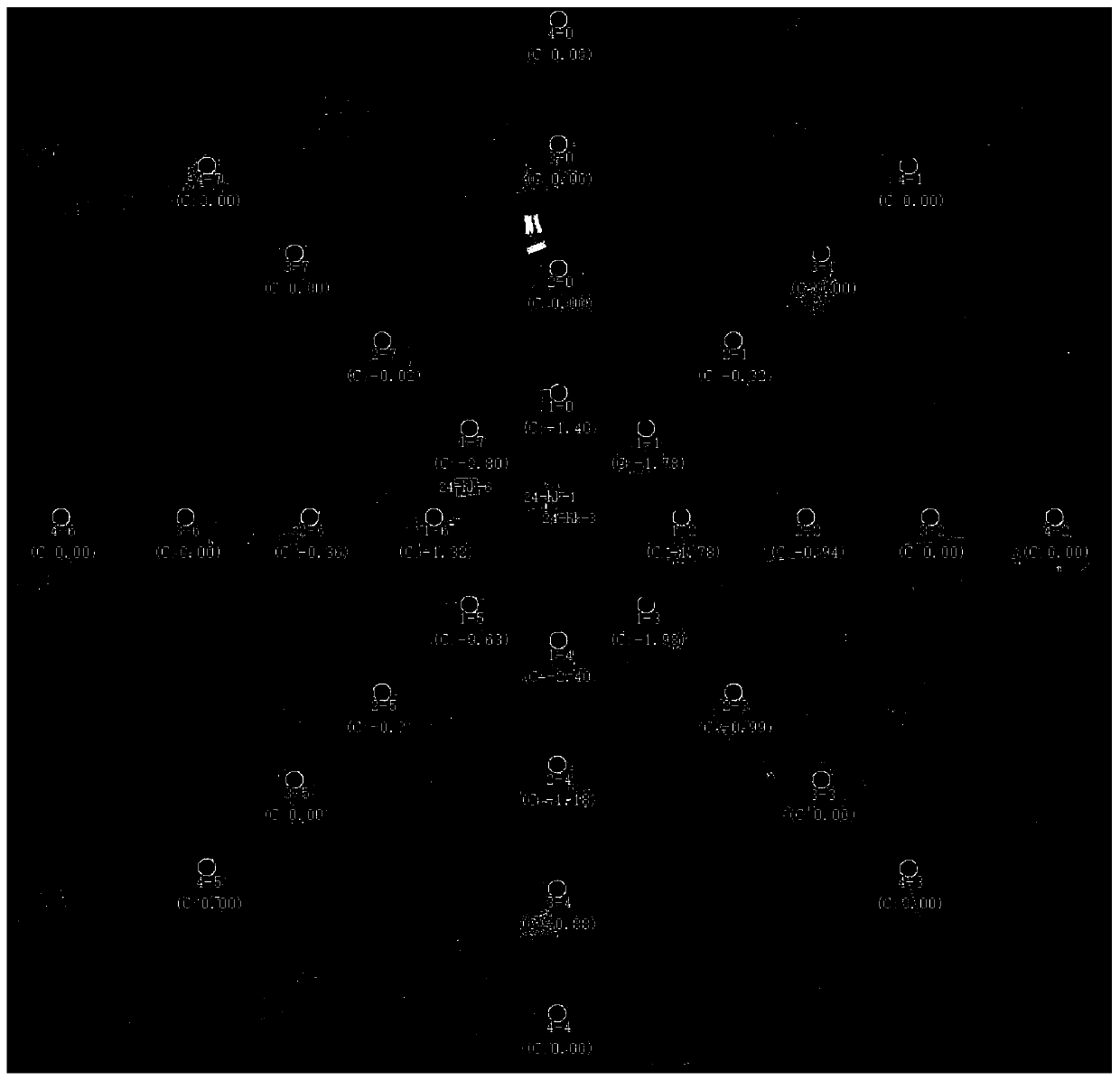
[0028] Step c, establishing a 360-degree azimuth-distance data matrix based on the installation position of the servo turntable optical monitoring equipment;

[0029] Step d, calibrate the pitch data of the servo turntable optical monitoring equipment for each unit of the azimuth distance data matrix, and complete the calibration;

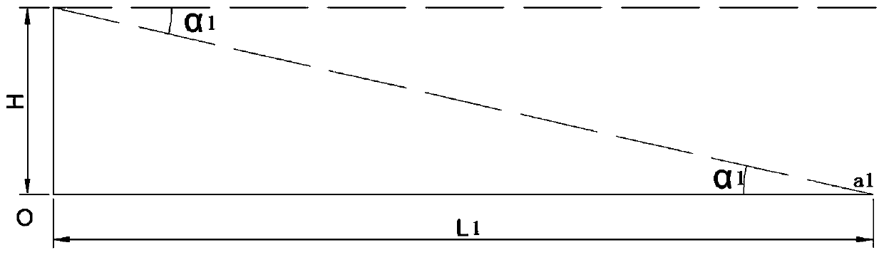
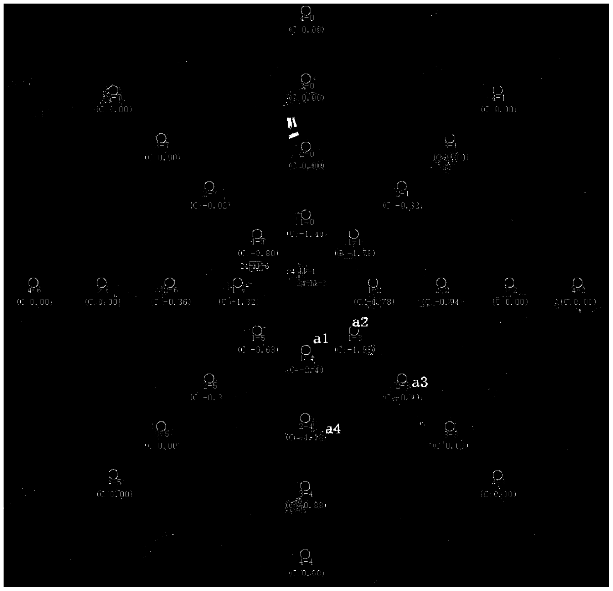
[0030] Step e, click any position according to the map, calculate the azimuth, pitch and distance parameters of the guiding servo turntable optical monitoring equipment through the matrix difference of the position poin...


PUM


Abstract

The invention discloses a pitching and azimuth calibration method for a remote optical rotary table based on a ground remote sensing image map, and belongs to the field of monitoring. The invention aims at a condition that a servo rotary table optical monitoring device is difficult to quickly guide to align with a target position. The method comprises the following steps: configuring a high-definition satellite ground image map of a monitored area; adding the installation position and the installation height of the servo rotary table optical monitoring device to the high-definition satellite ground image map; establishing a 360-degree equant azimuth distance data matrix based on the installation position of the servo rotary table optical monitoring device; calibrating pitching data of the servo rotary table optical monitoring device of each unit of the azimuth distance data matrix to finish calibration; clicking any position according to the map, calculating azimuth, pitching and distance parameters for guiding the servo rotary table optical monitoring device through a matrix difference to which a position point belongs, and controlling the servo rotary table optical monitoring device to complete equipment control. The method achieves the accurate guidance of the servo turntable optical monitoring equipment by easily clicking a map.

Description

technical field [0001] The invention belongs to the field of monitoring, in particular to a pitch and azimuth calibration method for a remote optical turntable based on a ground remote sensing image map. Background technique [0002] In the field of wide-area security monitoring, due to the vastness of the monitored area, complex features, and differences in terrain heights, it is difficult to directly determine the actual location of the observation site based on a single matching value of geographic space distance and pitch value. It is also difficult to quickly guide the servo turntable optical monitoring equipment to the target position, which brings troubles of cumbersome operation and inconvenient use to industry users. Contents of the invention [0003] The present invention overcomes the deficiencies of the prior art above, and provides a method for calibrating the pitch and azimuth of a remote optical turntable based on a ground remote sensing image map, using an ...

Claims


Application Information

Patent Timeline
Patent Type & Authority Applications(China)
IPC IPC(8): G01C25/00G01C21/00G01S19/42H04N7/18
CPCG01C21/005G01C25/00G01S19/42H04N7/18
Inventor 崔日华邹本泉李明迪赵叶辰任广宇
Owner DAQING ANRUIDA TECH DEV CO LTD
Why Eureka
Try Eureka