An overall step-by-step transfer device for a roller-row type omnidirectional drilling rig

A technology of moving device and roller row, which is used in earth-moving drilling, supporting device, drilling equipment, etc., can solve the problems of limited moving direction and inability to achieve precise movement, so as to improve the utilization rate and improve the adaptability of the well site. , the effect of prolonging the service life

Active Publication Date: 2016-06-01
中石化四机石油机械有限公司 +1
View PDF7 Cites 0 Cited by
  • Summary
  • Abstract
  • Description
  • Claims
  • Application Information

AI Technical Summary

Problems solved by technology

[0006] The purpose of the present invention is to overcome the shortcomings of the existing step-by-step transfer device for drilling rigs, such as the limited movement direction and the inability to achieve precise movement, etc., to provide a step-by-step transfer device that can accurately realize the overall drilling rig in an all-round way, and has a simple structure. It is easy to use, and can realize the rotation of the whole drilling rig, so that the drilling rig equipment can be shifted and reversed without disassembly, and the overall movement between wells with multiple well positions can be realized, which can meet the needs of small area and irregular well site conditions. need

Method used


Image

  • An overall step-by-step transfer device for a roller-row type omnidirectional drilling rig
  • An overall step-by-step transfer device for a roller-row type omnidirectional drilling rig
  • An overall step-by-step transfer device for a roller-row type omnidirectional drilling rig

Examples


Embodiment Construction

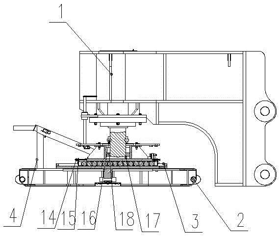
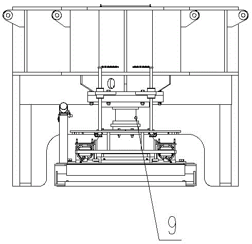
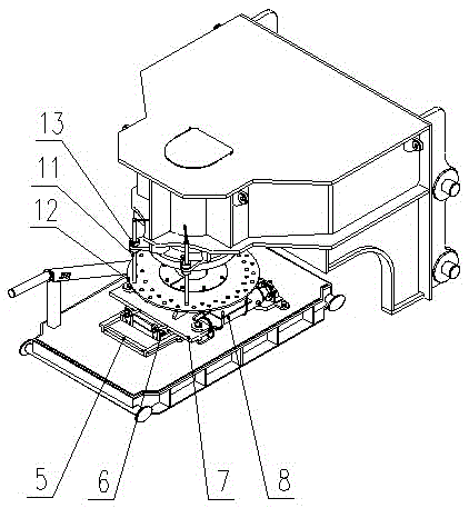
[0021] Attached below Figure 1-5 Specific embodiments of the present invention will be further described.

[0022] see Figure 1-5 : The bracket 1 is fixed to the base 19 of the cluster well drilling rig by connecting the pin shaft 21; the skid seat 2 is made of tailor-welded steel plates, which has a large grounding area and reduces the pressure on the ground; the reversing rotation mechanism 4 and the trolley 3 are installed on the skid seat 2 Top; the tray 5, the upper seat of the trolley 7, the roller row 6 and the translation cylinder 8 form the trolley 3; the roller row 6 is composed of 14 rollers installed on the frame, and the frame connects the rollers together; the translation cylinder 8 is a double cylinder , symmetrically arranged left and right, connected with the upper seat 7 of the trolley through the pin shaft, and the piston rod of the translation cylinder 8 is connected with the tray 5 through bolts; the tray 5 is welded by a steel plate and a right-angle s...


PUM


Abstract

Provided is a roller row type omni-directional drilling rig whole step-by-step moving device. A support is fixed to a cluster well rig substructure through connecting pin shafts, and a reversing rotating mechanism and a trolley are installed on a skid. The trolley is composed of a tray, an upper trolley base, a roller row and horizontal movement oil cylinders. The roller row is formed by installing 14 rollers on a frame, the horizontal movement oil cylinders are connected with the upper trolley base through pin shafts, piston rods of the horizontal movement oil cylinders are connected with the tray through bolts, guide rolling wheels are installed on the two sides of the front end of the upper trolley base, lug plates are installed at the two ends of the roller row, the roller row is connected with the upper trolley base through an adjusting rod, the trolley is connected with a jacking oil cylinder through a spherical surface tray and a clamping plate set, the jacking oil cylinder is installed on the support through bolts, and the spherical surface tray is installed on the upper trolley base. A limiting ring is installed on the spherical surface tray. Through the roller row type omni-directional drilling rig whole step-by-step moving device, on-site rotation of a whole drilling rig can be achieved, well site adaptability of the moving device is improved, the same moving device can be shared by multiple drilling rigs, and investment is saved.

Description

technical field [0001] The invention belongs to the field of oilfield drilling and repairing machines, and in particular relates to a step-by-step transfer device for the whole drilling machine. Background technique [0002] According to the needs of oil and gas field development, on offshore drilling platforms and specific areas of land oilfields, oil drilling rigs need to use close-distance network or linear multi-well cluster well drilling operations. This operation mode requires the drilling rig to move as a whole. [0003] The overall step-by-step transfer device of the all-round drilling and repairing machine uses the jacking cylinder to lift the drilling rig as a whole, and then uses the translation cylinder to push and pull the device for step-by-step translation, which can realize the overall omnidirectional translation of the drilling rig, and has a small area on the well site It is highly applicable in the drilling operation of cluster wells with arbitrary arrange...

Claims


Application Information

Patent Timeline
Patent Type & Authority Patents(China)
IPC IPC(8): E21B15/00E21B7/02
CPCE21B7/02E21B15/003
Inventor 高迅陈新龙徐军彭太锋夏争光
Owner 中石化四机石油机械有限公司
Why Eureka
Try Eureka