Eureka AIR delivers breakthrough ideas for toughest innovation challenges, trusted by R&D personnel around the world.

Permanent magnet synchronous spiral linear motor

A linear motor, permanent magnet synchronous technology, applied in the field of electric motors, can solve the problems of increasing the complexity of the motion mechanism, increase the complexity of control, etc., and achieve the effects of high linear motion accuracy, small starting current, and simple motion mechanism

Pending Publication Date: 2019-09-24
徐建宁
View PDF0 Cites 0 Cited by
  • Summary
  • Abstract
  • Description
  • Claims
  • Application Information

AI Technical Summary

Problems solved by technology

[0002] If the conventional permanent magnet motor achieves linear motion, an intermediate conversion mechanism is required to convert the rotary motion into linear motion, which will increase the complexity of the motion mechanism. However, because the speed ratio between the electromagnetic field and the linear motion is zero, the flat linear motor needs to obtain High-precision displacement will increase the complexity of control

Method used


Image

  • Permanent magnet synchronous spiral linear motor
  • Permanent magnet synchronous spiral linear motor
  • Permanent magnet synchronous spiral linear motor

Examples


Embodiment Construction

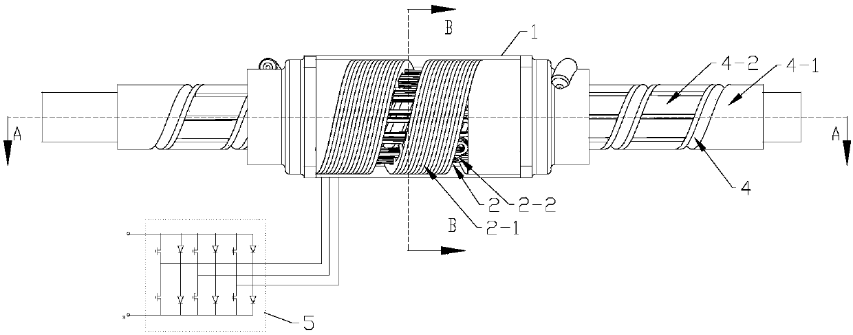
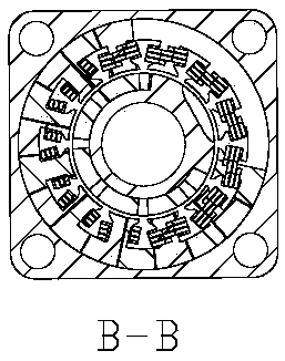
[0018] Such as figure 1 , 2 , shown in 3: a permanent magnet synchronous helical linear motor, comprising: a shell 1, an armature 2 set with the shell 1, an end cover 3 with a ball nut 3-2 connected to the two ends of the shell 1, and the armature 2 and The rotatable exciter 4 set by the end cover 3, the control circuit 5 connected to the coil group 2-2 of the armature 2 to supply power to the armature 2; the armature 2 is composed of a spiral iron core 2-1 and a coil group 2-2; the exciter 4 is composed of a cylindrical yoke 4-1 and a number of permanent magnet tiles 4-2 uniformly distributed on the circumferential surface of the yoke 4-1 in a spiral shape; it is characterized in that: The spiral core 2-1 of the armature 2 is to form a number of magnetic poles by punching evenly distributed notches in the inner circle of several annular silicon steel sheets, break a gap at the same position of several annular silicon steel sheets, and place several annular silicon steel shee...


PUM


Abstract

The invention discloses a permanent magnet synchronous spiral linear motor, which is characterized in that the iron core of a motor armature is made into a plurality of circles of a spiral iron core with an equal pitch, a plurality of notches uniformly distributed on an inner circle of the spiral iron core are embedded with a three-phase coil group capable of axially penetrating through the plurality of circles of the spiral iron core, or three-phase windings are sequentially embedded along the spiral direction of the spiral iron core; an excitation body of the motor is formed by spirally attaching a plurality of permanent magnet tiles with the N poles and S poles being alternately arranged to the periphery of a cylindrical magnetic yoke with a ball thread; and the excitation body and the armature are coaxially sleeved together, and the three-phase coil group of the armature is powered by a control circuit to form a spiral magnetic field so as to drag the excitation body to perform synchronous spiral motion. The permanent magnet synchronous spiral linear motor produces compound motion, that is, there is a speed ratio between the rotary motion and the linear motion, and the speed ratio can increase the thrust of the motor and the speed of the linear motion; and the high-precision linear motion can be obtained without an intermediate conversion mechanism.

Description

technical field [0001] The invention relates to a permanent magnet synchronous helical linear motor, in particular to the field of electric motors. Background technique [0002] If the conventional permanent magnet motor achieves linear motion, an intermediate conversion mechanism is required to convert the rotary motion into linear motion, which will increase the complexity of the motion mechanism. However, because the speed ratio between the electromagnetic field and the linear motion is zero, the flat linear motor needs to obtain High-precision displacement will increase the complexity of control. Contents of the invention [0003] The invention provides a permanent magnet synchronous helical linear motor. The iron core of the motor armature is made into a number of helical iron cores with equal pitches, and a number of slots uniformly distributed in the inner circle of the helical iron core are embedded with a shaft. The three-phase coil group that runs through severa...

Claims


Application Information

Patent Timeline
Patent Type & Authority Applications(China)
IPC IPC(8): H02K41/03
CPCH02K41/031
Inventor 徐建宁
Owner 徐建宁
Why Eureka
Eureka Blog
Learn More