Bend type double-layer mist catching device for flue gas desulfurization tower

A desulfurization tower and flue gas technology, which is applied in the field of flue gas desulfurization, can solve the problems of reduced demisting efficiency, inability to adjust, and decline in fogging effect, and achieve the effect of improving demisting effect

Active Publication Date: 2019-09-27
台州临港热电有限公司
View PDF5 Cites 0 Cited by
  • Summary
  • Abstract
  • Description
  • Claims
  • Application Information

AI Technical Summary

Problems solved by technology

[0003] During the demisting process of the mist trapping device, there is a high requirement for the flow rate of the flue gas. If the flue gas flow rate is too high, it will easily cause the flue gas to carry water again, and when the flue gas passes through the mist trapping plate quickly , the mist cannot be formed into droplets in a timely manner, thereby reducing the efficiency of demisting, and the traditional mist-catching devices have fixed-installed mist-catching plates, which cannot be adjusted in time according to the flue gas flow rate. During the demisting process, The droplets will gather and drip at the turning of the fog catching plate, but at the same time, the impurities and dust in the flue gas will also accumulate at the turning. After a long period of use, the fog catching device will be blocked, not only The effect of fog is reduced, and the smoke cannot be discharged normally.

Method used


Image

  • Bend type double-layer mist catching device for flue gas desulfurization tower
  • Bend type double-layer mist catching device for flue gas desulfurization tower
  • Bend type double-layer mist catching device for flue gas desulfurization tower

Examples


Embodiment Construction

[0028] The following will clearly and completely describe the technical solutions in the embodiments of the present invention with reference to the accompanying drawings in the embodiments of the present invention. Obviously, the described embodiments are only some, not all, embodiments of the present invention. Based on the embodiments of the present invention, all other embodiments obtained by persons of ordinary skill in the art without making creative efforts belong to the protection scope of the present invention.

[0029] The embodiment of the double-layer mist trapping device for the bent type flue gas desulfurization tower is as follows:

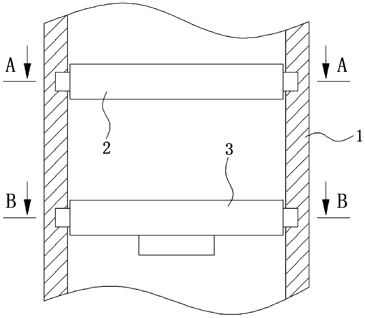
[0030] see Figure 1-9 , a double-deck mist trapping device for a bent flue gas desulfurization tower, comprising a tower body 1 , an upper mist trapping device 2 and a lower mist trapping device 3 .

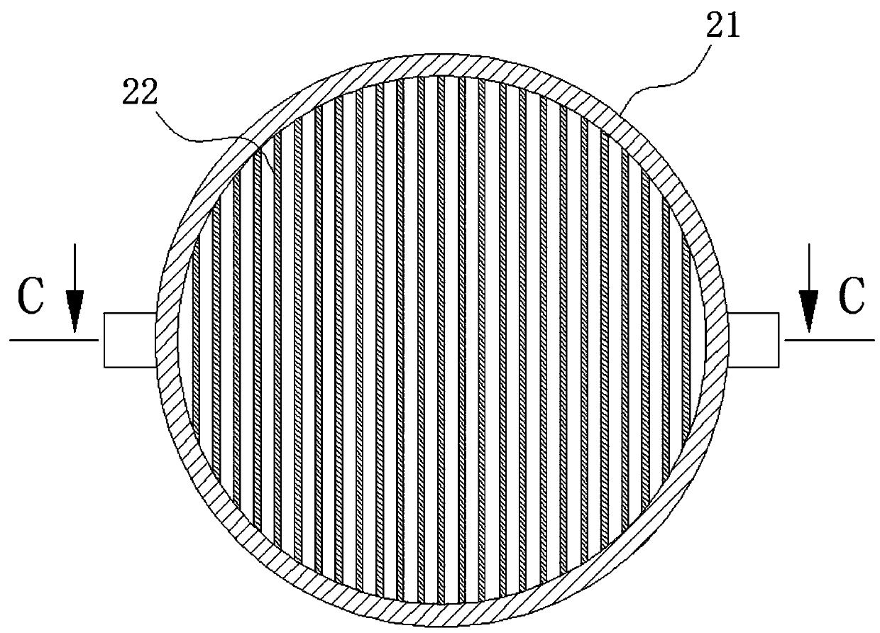
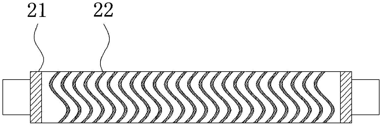
[0031] Wherein, the upper mist trapping device 2 includes a first cylinder 21 and a corrugated plate 22 .

[0032] Wherein, the low...


PUM


Abstract

The invention provides a bend type double-layer mist catching device for a flue gas desulfurization tower, and relates to the technical field of flue gas desulfurization. The bend type double-layer mist catching device for the flue gas desulfurization tower comprises a tower body, an upper mist catching device body and a lower mist catching device body are fixedly arranged in the tower body, a first cylindrical barrel is fixedly arranged inside the tower body, a corrugated plate is fixedly arranged inside the first cylindrical barrel, and a second cylindrical barrel is fixedly arranged inside the tower body. According to the bend type double-layer mist catching device for the flue gas desulfurization tower, when the flow rate of flue gas becomes higher, the bend amplitude of mist collecting plates can be increased and can be recovered after the flow rate of the flue gas becomes normal, and therefore the demisting effect of the high-speed flue gas is improved while the demisting efficiency is not influenced; and in addition, in the process when the turning angle of the mist catching plates is changed, dust accumulated at the turning position of the mist catching plates can be better separated from the mist catching plates and can fall off with the cooperation of fallen liquid drops of the upper collecting device, and therefore the blockage of the collecting device is effectively prevented.

Description

technical field [0001] The invention relates to the technical field of flue gas desulfurization, in particular to a double-layer mist trapping device for a bent type flue gas desulfurization tower. Background technique [0002] The flue gas desulfurization tower is a tower-type equipment for desulfurization treatment of industrial waste gas. It has the advantages of easy maintenance, and can achieve dust removal and desulfurization and denitrification effects at the same time by preparing different dust removers. It is most common in coal-fired power plants, and in desulfurization towers The top of the tower will be equipped with a mist trapping device, its main function is to trap the mist particles and slurry droplets entrained in the flue gas during the spray absorption process, so as to prevent the desulfurization liquid from being carried out by the gas. [0003] During the demisting process of the mist trapping device, there is a high requirement for the flow rate of t...

Claims


Application Information

Patent Timeline
IPC IPC(8): B01D45/08B01D45/18
CPCB01D45/08B01D45/18
Inventor 楼佩琦
Owner 台州临港热电有限公司
Why Eureka
Try Eureka