
Intelligent adjustable steel belt transmission tensioning mechanism

A tensioning mechanism and steel belt transmission technology, applied in conveyors, transportation and packaging, etc., can solve problems such as affecting the transmission effect, being tilted by the top, shortening the service life of the steel belt, etc., to ensure normal transmission, simple device structure, good contact effect

Pending Publication Date: 2019-09-27
湄洲湾职业技术学院
View PDF0 Cites 3 Cited by
  • Summary
  • Abstract
  • Description
  • Claims
  • Application Information

AI Technical Summary

Problems solved by technology

In the existing steel belt tensioning mechanism, if the tension roller does not tension the steel belt at the center of the steel belt width during the tensioning process, the steel belt is easily subjected to eccentric force during tension, and thus is tilted by the top. Serious wear and tear on the steel belt will seriously shorten the service life of the steel belt, and also affect the transmission effect, making the transmission not stable enough, and most of the current steel belt tensioning mechanisms cannot conveniently make the tension roller located at the width of the steel belt The steel belt is tensioned at the central position. For this reason, an intelligent adjustable steel belt transmission tensioning mechanism is urgently needed

Method used


Image

  • Intelligent adjustable steel belt transmission tensioning mechanism
  • Intelligent adjustable steel belt transmission tensioning mechanism
  • Intelligent adjustable steel belt transmission tensioning mechanism

Examples


Embodiment Construction

[0025] The technical solutions in the embodiments of the present invention will be clearly and completely described below in conjunction with the accompanying drawings in the embodiments of the present invention. Obviously, the described embodiments are only a part of the embodiments of the present invention, rather than all the embodiments.

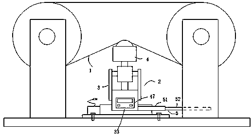
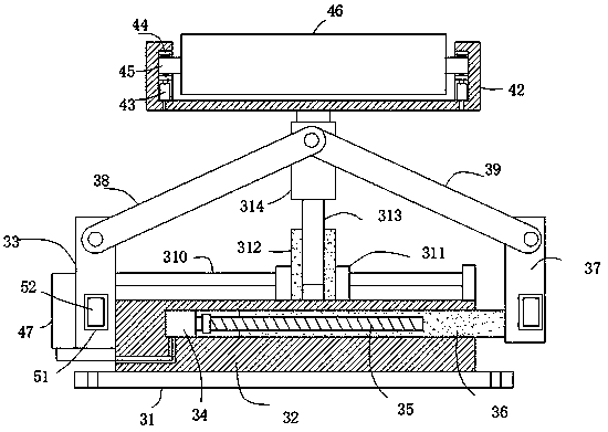
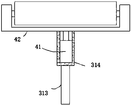
[0026] Reference Figure 1-6 , An intelligent adjustable steel belt drive tensioning mechanism, comprising a tensioning mechanism body 2 that is tightly matched with the steel belt 1. The tensioning mechanism body 2 includes a centering assembly 3 on which a force application component is installed 4. A positioning assembly 5 is installed on the centering assembly 3, and the force application assembly 4 is aligned with the center position of the steel belt 1 under the action of the centering assembly 3 and is tightly matched with the steel belt 1;

[0027] The centering assembly 3 includes a fixed bottom plate 31, the top surface of the fixed...


PUM


Abstract

The invention discloses an intelligent adjustable steel belt transmission tensioning mechanism and relates to the field of steel belt transmission. According to the problems that when an existing steel belt tensioning mechanism is used for tensioning a steel belt, a contact effect cannot be ensured well, the steel belt is likely to be damaged, and the service life of the steel belt is shortened, the following scheme is put forwards. The scheme includes that the intelligent adjustable steel belt transmission tensioning mechanism comprises a tensioning mechanism body matched with the steel belt in a tensioned manner; the tensioning mechanism body comprises a centering assembly; a force applying assembly is installed on the centering assembly; a positioning assembly is installed on the centering assembly; and the force applying assembly is used for being aligned with the center position of the steel belt under the effect of the centering assembly and is matched with the steel belt in a tensioned manner. By means of the intelligent adjustable steel belt transmission tensioning mechanism, the whole mechanism can be used for tensioning the steel belt, in addition, the tensioning force is adjustable, meanwhile the contact effect between a transverse tensioning roller and the steel belt is good, the steel belt cannot be ejected to be eccentric, normal transmission of the steel belt can be ensured, damage to the steel belt can also be avoided, the whole device is simple in structure, and the manufacturing cost is low.

Description

Technical field [0001] The invention relates to the field of steel belt transmission, in particular to an intelligent adjustable steel belt transmission tensioning mechanism. Background technique [0002] The use of steel belt transmission is currently a relatively common transmission method. The steel belt currently produced will fall due to its own weight, which will cause slack. Corresponding devices are required to tension the steel belt. In the existing steel belt tensioning mechanism, if the tensioning roller does not tension the steel belt at the center of the width of the steel belt during the tensioning process, the steel belt will be easily subjected to eccentric force during tensioning, thereby being tilted. Severe wear to the steel belt will seriously shorten the service life of the steel belt, and also affect the transmission effect, making the transmission not stable enough, and most of the current steel belt tensioning mechanisms cannot conveniently position the te...

Claims


Application Information

Patent Timeline
Patent Type & Authority Applications(China)
IPC IPC(8): B65G23/44B65G15/48
CPCB65G15/48B65G23/44
Inventor 张星徐维雄曹劲吴丽明
Owner 湄洲湾职业技术学院
Learn More