Bridge deflection change measuring method, device and equipment

A bridge deflection and measurement method technology, which is applied in the field of measurement, can solve the problems of the measurement accuracy affected by the attitude of the camera itself, and the measurement accuracy of long-distance imaging affected by the atmospheric environment, and achieve the effect of avoiding the influence of the atmospheric environment

Active Publication Date: 2019-09-27
SUN YAT SEN UNIV
View PDF5 Cites 11 Cited by
  • Summary
  • Abstract
  • Description
  • Claims
  • Application Information

AI Technical Summary

Problems solved by technology

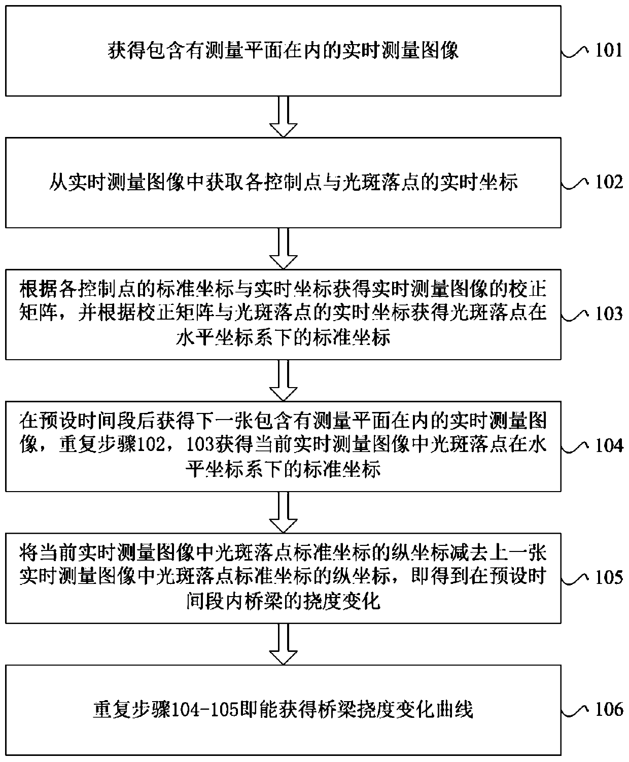
[0004] The present invention provides a bridge deflection change measurement method, device and equipment, which are used to overcome the shortcomings of the prior art in the imaging measurement of the bridge deflection, such as t

Method used


Image

  • Bridge deflection change measuring method, device and equipment
  • Bridge deflection change measuring method, device and equipment
  • Bridge deflection change measuring method, device and equipment

Examples


Embodiment Construction

[0044] The following will clearly and completely describe the technical solutions in the embodiments of the present invention with reference to the accompanying drawings in the embodiments of the present invention. Obviously, the described embodiments are only part of the embodiments of the present invention, not all of them. Based on the embodiments of the present invention, all other embodiments obtained by persons of ordinary skill in the art without creative efforts fall within the protection scope of the present invention.

[0045] It should be noted that all directional indications (such as up, down, left, right, front, back...) in the embodiments of the present invention are only used to explain the relationship between the components in a certain posture (as shown in the accompanying drawings). Relative positional relationship, movement conditions, etc., if the specific posture changes, the directional indication will also change accordingly.

[0046] In addition, in t...


PUM


Abstract

The invention discloses a bridge deflection change measuring method, device and equipment. A vertical plane is selected or arranged at any position of the bridge as a measuring plane; at least four positioning pieces containing control point images are arranged in the measuring plane; the control point images in all control pieces are not collinear at the same time; the method includes the steps of measuring the standard coordinates of the control points in the control point images in the positioning pieces under a horizontal coordinate system, placing a laser at any position, enabling laser spots emitted by the laser to fall into the measuring plane, placing a camera at any position, and enabling the measuring plane to be located in a shooting view field of the camera. A mode of combining laser indication with camera short-distance imaging is adopted, so that the problems that long-distance imaging is influenced by the atmospheric environment and measurement precision is influenced by postures of the camera can be avoided; through control point imaging processing, the influence of camera shaking on the measurement can be eliminated, and deflection measurement can be flexibly carried out on bridges on the water surface, canyons and other positions. The method is applied to the technical field of measurement.

Description


Claims


Application Information

Patent Timeline
Owner SUN YAT SEN UNIV
Why Eureka
Try Eureka