Multi-beam deformation detecting device and use method thereof

A detection device, multi-beam technology, applied in measurement devices, optical devices, instruments, etc., can solve problems such as real-time prevention and accurate detection of obstacles in bridge detection, weather changes and air turbulence, and bridge deflection cannot be monitored online for a long time. , to achieve the effect of long-term online monitoring, simple structure and accurate deformation

Inactive Publication Date: 2010-06-02
CHONGQING UNIV
View PDF1 Cites 17 Cited by
  • Summary
  • Abstract
  • Description
  • Claims
  • Application Information

AI Technical Summary

Problems solved by technology

[0006] However, because they are easily affected by background stray light, the laser method, laser image method and photoelectric imaging method are only effective in the occasions with a short distance and good weather conditions, and high-precision detection in other situations cannot be realized
At the same time, since the bridge deflection cannot be monitored online for a long time, it brings certain obstacles to the real-time prevention and accurate detection of bridge detection
[0007] Disadvantages of existing deformation detection devices and methods: greatly affected by weather changes and air turbulence, the detection accuracy is not high, and long-term online monitoring is not possible

Method used


Image

  • Multi-beam deformation detecting device and use method thereof
  • Multi-beam deformation detecting device and use method thereof
  • Multi-beam deformation detecting device and use method thereof

Examples


Embodiment 1

[0033] Embodiment 1, applying the multi-beam deformation detection device provided by the present invention to bridge deformation detection:

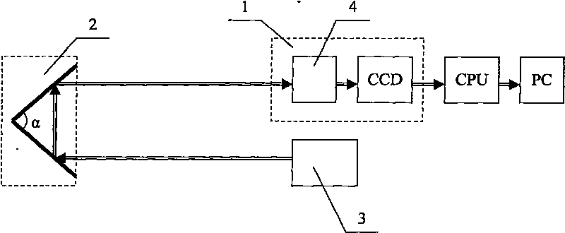
[0034] Such as figure 1 As shown, the multi-beam deformation detection device is composed of a detector 1, a prism reflecting target 2 and a laser group 3. The detector 1 and the laser group 3 are installed on the shore, and the prism reflecting target 2 is installed under the main girder of the bridge. Surface, the angle α between the two reflective surfaces of the prism reflective target 2 = 64°. The laser beam group emitted by the laser group 3 is reflected by the first prism surface of the prism reflection target 2 to the second prism surface of the prism reflection target 2, and after being reflected by the second prism surface, it is received by the optical antenna 4 and sent to the photoelectric image sensor CCD. An overlapping light spot is formed on the camera, and the digital signal processor DSP takes out the information of ...

Embodiment 2

[0044] Embodiment 2, the multi-beam deformation detection device provided by the present invention is applied to landslide detection: a prism reflection target 2 is installed on the top of the mountain to be measured, a detector 1 and a laser group 3 are installed at the measurement point, and the laser group 3 emits After the laser beam group is reflected by the prism reflection target 2, overlapping spots are formed on the detector 1, and the centroid of the overlapping spots is determined by the photoelectric tracking macropixel iterative centroid method. After 3-6 months or more, after deformation interference occurs at the point to be measured, the moving distance H of the center of mass of the overlapping light spots is obtained to determine the deformation of the point to be measured on the mountain, and then determine the deformation of the mountain. If the mountain body undergoes major changes, corresponding landslide prevention measures should be taken.

[0045] The ...


PUM


Abstract

The invention relates to a multi-beam deformation detecting device which comprises a probe, a digital signal processor DSP, a personal computer PC, a laser group and a prism reflection target, wherein the prism reflection target is arranged on a point to be tested, the probe and the laser group are arranged on a measuring point, a laser beam group emitted from the laser group is reflected through the prism reflection target by adjusting the laser group and then forms an overlapped light spot on the probe, a barycenter of the overlapped light spot is determined by utilizing a photoelectronic tracing macro pixel iteration barycenter method, and the deformation of the point to be tested is further determined through the barycenter offset distance. The invention can effectively avoid the influences on environmental change, air turbulence and stray light, can realize long-term online monitoring, and has accurate measurement data, high detection precision, simple structure, low cost and convenient operation.

Description

technical field [0001] The invention belongs to the field of deformation measurement, in particular to a device for detecting the deformation of a point to be measured by measuring the spot movement of multiple laser beams and a method for using the same. Background technique [0002] Detecting the subsidence and movement of modern large buildings such as bridges plays an important role in modern road and bridge construction. The optical method can realize high-precision real-time detection of bridge deflection. Among optical methods, laser method, laser imaging method and photoelectric imaging method are three important methods. [0003] Liu Niandong of Chongqing University and others used the laser method to measure bridge deflection: using the good directionality of the laser, the laser fixed at the measured point of the bridge changes with the deflection of the bridge, and the center of the laser spot irradiated on the CCD also changes accordingly. The center position ...

Claims


Application Information

Patent Timeline
Patent Type & Authority Applications(China)
IPC IPC(8): G01B11/16
Inventor 刘丹平张磊胡学斌曾孝平冯文江唐朝伟
Owner CHONGQING UNIV
Why Eureka
Try Eureka