
Robotic system and method for operating on workpiece

A robot system and robot technology, applied in the field of robot systems, can solve problems such as labor costs

Pending Publication Date: 2019-10-01
THE BOEING CO
View PDF0 Cites 6 Cited by
  • Summary
  • Abstract
  • Description
  • Claims
  • Application Information

AI Technical Summary

Problems solved by technology

Additionally, some automated methods require manually customizing the cleaning process for unique mandrel configurations and this results in significant labor costs

Method used


Image

  • Robotic system and method for operating on workpiece
  • Robotic system and method for operating on workpiece
  • Robotic system and method for operating on workpiece

Examples


Embodiment Construction

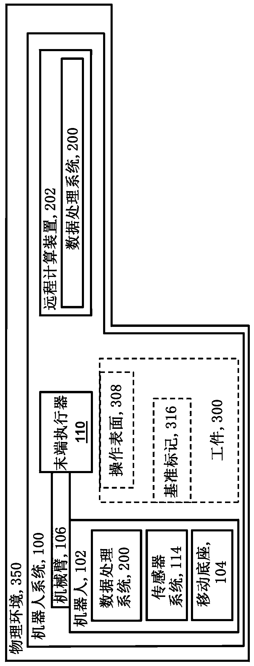
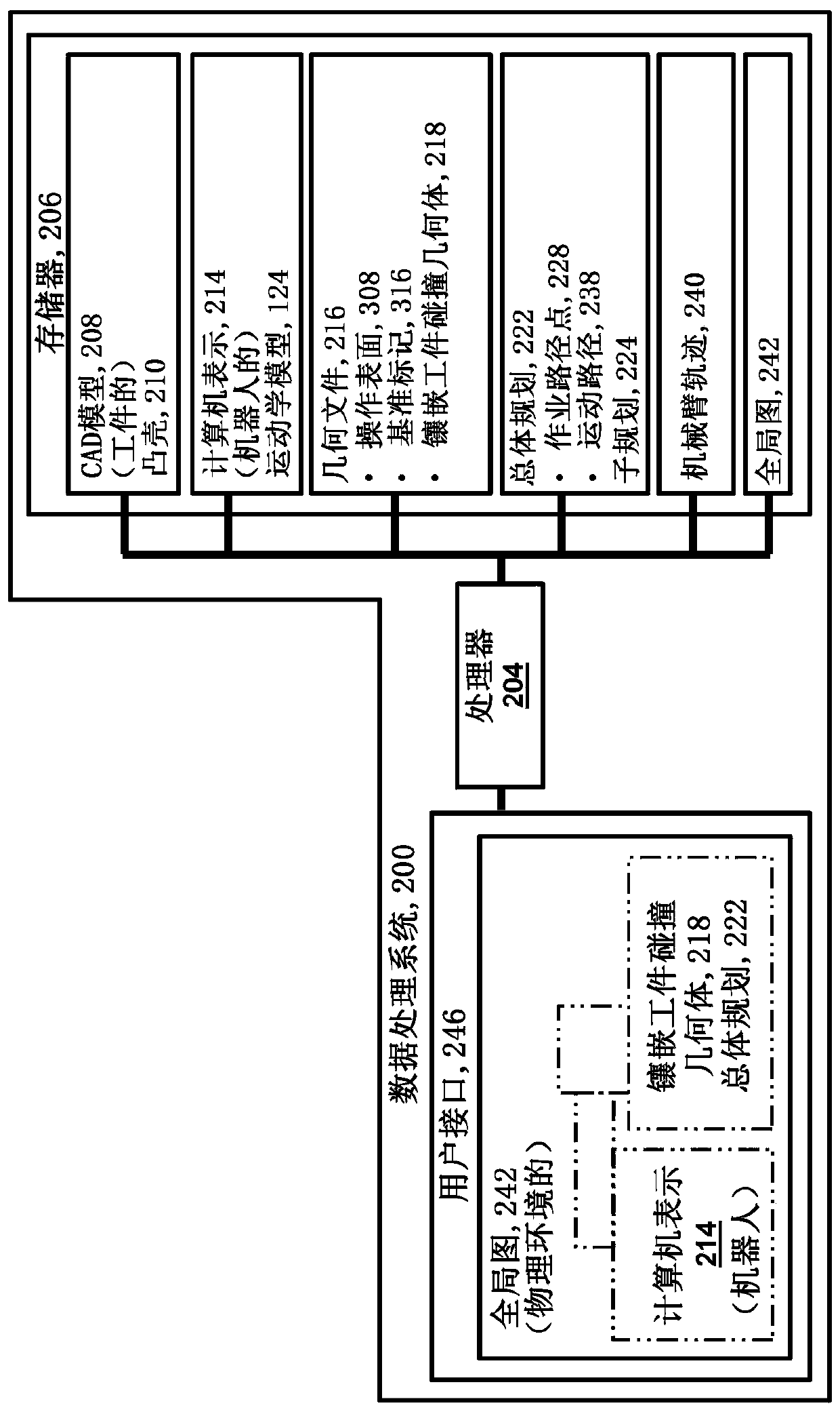
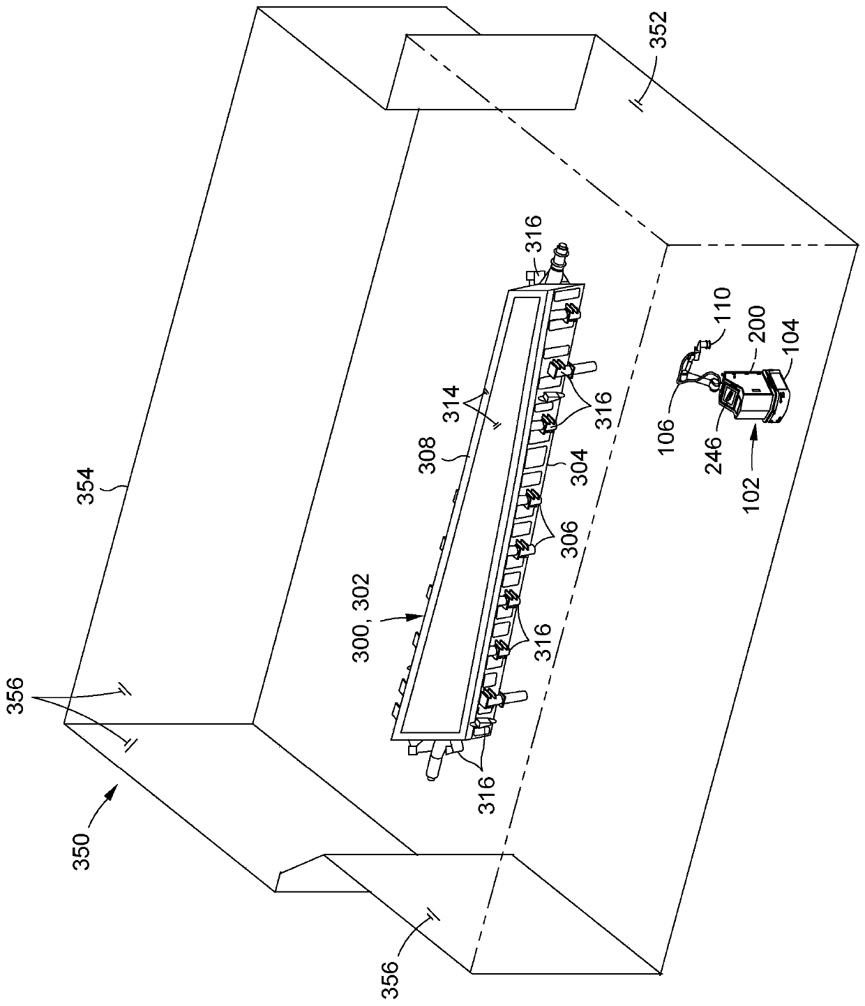
[0041] Referring now to the drawings, in which the drawings are for purposes of illustrating preferred and various embodiments of the present disclosure, figure 1 Shown in is a block diagram of an example of a robotic system 100 with features for automatically aligning with a physical environment 350 ( image 3 At least one robot 102 operating on the operating surface 308 of the workpiece 300 in ). The robot 102 has a mobile base 104 that may be configured as an automated guided vehicle for moving the robot 102 along a surface such as a floor of a production facility (eg, a physical environment). The robot 102 has a robotic arm 106 and an end effector 110 coupled to the robotic arm 106 . End effector 110 may be configured to perform operations on operative surface 308 of workpiece 300 . In the present disclosure, the workpiece 300 is configured as a twisted mandrel 302 ( image 3 ), which has a twisting surface 314 for twisting a composite part (not shown) ( image 3 ). E...


PUM


Abstract

The application relates to a robotic system and method for operating a workpiece. The robotic system includes a robot and a processor configured to autonomously generate a master plan for movement ofan end effector of the robot for operating on an operating surface of a workpiece in a physical environment. The master plan is based on a computer aided design (CAD) model of the workpiece and defines movement paths of the end effector based on a reach distance of a robotic arm of the robot at each of a plurality of working waypoints defined in the master plan and corresponding to fiducial markers on the workpiece. The processor registers the robot to the workpiece, iteratively adjusts an approximate workpiece position in a world map until matching an actual workpiece position in the physicalenvironment, and constructs and executes a robotic arm trajectory causing the end effector to operate on the operating surface along the movement paths defined in the master plan.

Description

technical field [0001] The present disclosure relates generally to robotic systems, and more particularly, to methods for systems that utilize one or more mobile robots to automatically manipulate workpieces. Background technique [0002] Manufacturing composite parts in a production process may involve twisting plies of composite material onto the twisting surfaces of twisting mandrels. Every time a composite part is twisted, the twisting surface must first be cleaned to remove contamination such as burnt resin, adhesives, sealing chemicals and / or other consumables that may have been present from previous use of the twisting mandrel. Cleaning of the twisted surface can be performed by a technician using a handheld orbital sander. However, manual cleaning is a time-consuming process for large twisted mandrels. [0003] Automated methods have been developed to reduce the amount of time required for twisting mandrel cleaning. One approach entails constructing a mandrel clea...

Claims


Application Information

Patent Timeline
Patent Type & Authority Applications(China)
IPC IPC(8): B25J9/16
CPCB25J9/1664B25J9/1605B25J9/1682B25J9/1669B25J9/1697G05B19/4097G05D1/0214B25J9/162B25J9/1666B25J9/1671B25J11/0085Y10S901/01Y10S901/09Y10S901/47Y10S901/49
Inventor 马丁·A·沙尔斯基多米尼克·维日比茨基菲利普·詹姆斯·豪斯勒
Owner THE BOEING CO
Learn More