
Textile silk yarn winding device

A winding device and silk thread technology, which is applied in the directions of transportation and packaging, delivery of filamentous materials, and thin material processing, etc., can solve problems such as easy shaking of the yarn bobbin, reduction of the winding amount of the bobbin, and easy tearing of the silk thread, etc., to achieve Prevent rotation and shaking, ensure winding quality, and ensure continuity

Active Publication Date: 2019-10-08
嘉兴市恒悦纺织股份有限公司
View PDF7 Cites 8 Cited by
  • Summary
  • Abstract
  • Description
  • Claims
  • Application Information

AI Technical Summary

Problems solved by technology

[0003] The current winding device does not have a wire arrangement device when in use. When the silk thread is wound on the bobbin, it will cause the thread to wind around a certain part of the bobbin, resulting in uneven winding of the silk thread, reducing the winding amount of the bobbin, and reducing the The utilization rate of yarn reels, and most of the current yarn reels are directly inserted on the rotating shaft, without fixing devices, the yarn reels are prone to shaking, easy to break the silk thread, resulting in wrong winding of the silk thread, and unnecessary troubles for the winding of the silk thread

Method used


Image

  • Textile silk yarn winding device
  • Textile silk yarn winding device
  • Textile silk yarn winding device

Examples


Embodiment Construction

[0021] The following will clearly and completely describe the technical solutions in the embodiments of the present invention with reference to the accompanying drawings in the embodiments of the present invention. Obviously, the described embodiments are only some, not all, embodiments of the present invention. Based on the embodiments of the present invention, all other embodiments obtained by persons of ordinary skill in the art without making creative efforts belong to the protection scope of the present invention.

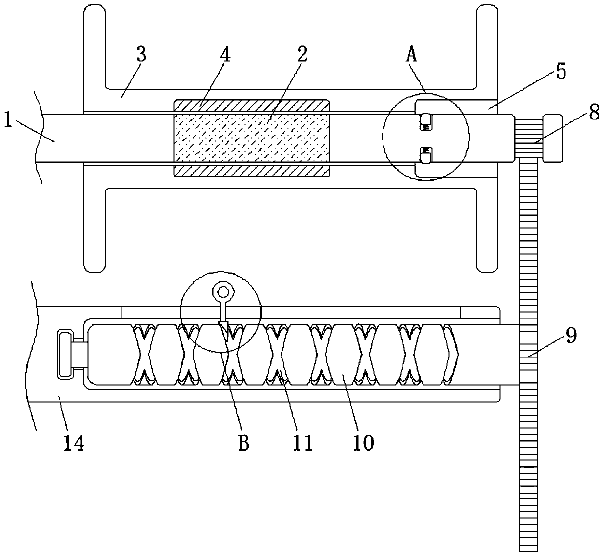
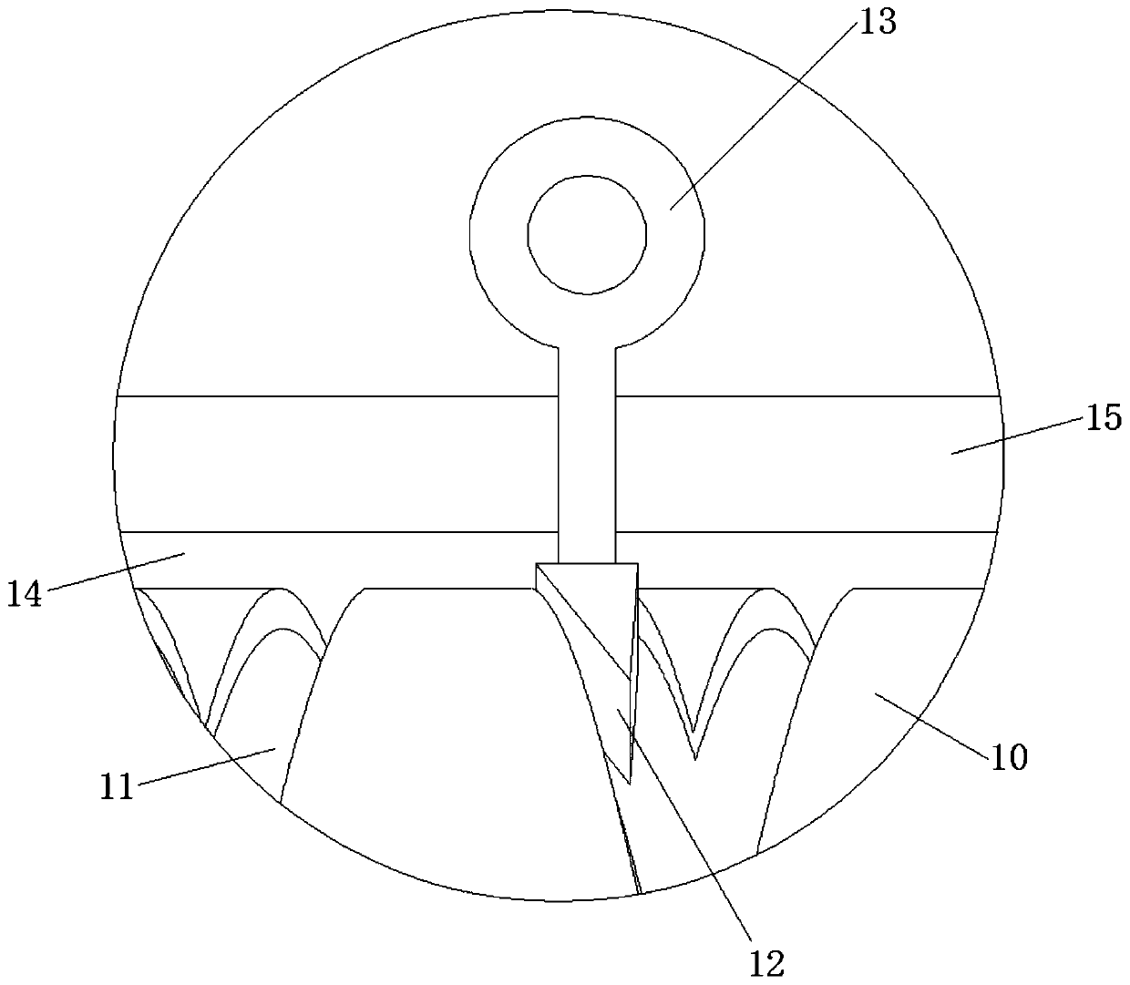
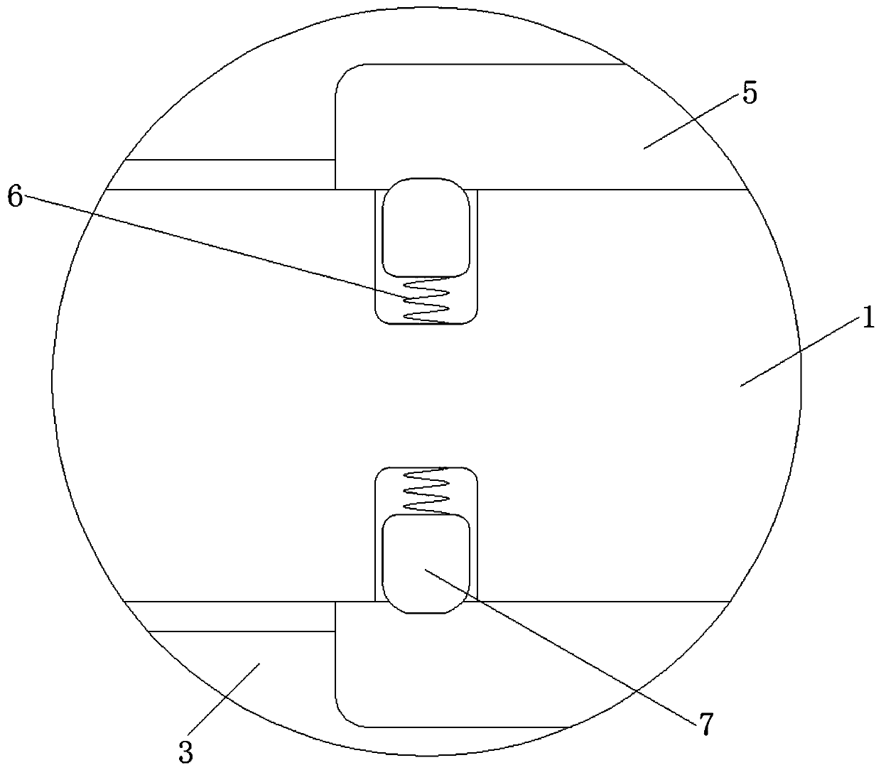
[0022] see Figure 1-6 , a textile thread winding device, comprising a rotating shaft 1, the rotating shaft 1 plays the role of transmission, the left side of the rotating shaft 1 is fixedly connected with the motor and the length of the rotating shaft 1 is greater than the length of the bobbin 3, and the material of the friction ring 2 is rubber material And the length of the friction ring 2 is equal to the length of the scrub 4, the outer side of the rotatin...


PUM


Abstract

The invention discloses a textile silk yarn winding device and relates to the technical field of textile. The textile silk yarn winding device comprises a rotating shaft; a friction ring is fixedly connected to the outer side of the rotating shaft; a yarn winder is inserted connected with the outer side of the rotating shaft in an inserting mode; the inner wall of the yarn winder is fixedly connected with grinding sand; the middle of the yarn winder is provided with a stepped groove; the inner wall of the rotating shaft is fixedly connected with first springs which are evenly distributed; theouter sides of the first springs are fixedly connected with a movable block which is movably connected with the inner wall of the rotating shaft; and the right side of the rotating shaft is provided with a tooth groove. According to the textile silk yarn winding device, through coordinate application of the movable block and the friction ring, when silk yarns need to be wound, the yarn winder is arranged on the outer side of the rotating shaft in a sleeving mode, after sleeving, the friction ring and makes contact with the grinding sand, friction force of the yarn winder drum and the rotatingshaft are increased, meanwhile, when the rotating shaft drives the yarn winder to rotate, the movable block will throw the rotating shaft away under the action of centrifugal force, the movable blockis clamped with the stepped groove, the yarn winder is fixed on the rotating shaft, thus, the effect of fixing the yarn winder is achieved, the yarn winder is effectively prevent from rotating and swaying, and the silk yarn winding quality is ensured.

Description

technical field [0001] The invention relates to the technical field of textile equipment, in particular to a textile thread winding device. Background technique [0002] The silk winding device plays an important role in textile equipment. The textile thread is wound on the bobbin through the winding device, which is convenient for the storage and transportation of the silk thread, and makes the use of the silk thread more convenient. The following problems will arise: [0003] The current winding device does not have a wire arrangement device when in use. When the silk thread is wound on the bobbin, it will cause the thread to wind around a certain part of the bobbin, resulting in uneven winding of the silk thread, reducing the winding amount of the bobbin, and reducing the The utilization rate of the yarn bobbin, and most of the current yarn bobbins are directly inserted on the rotating shaft without a fixing device, the yarn bobbin is easy to shake, and the silk thread i...

Claims


Application Information

Patent Timeline
Patent Type & Authority Applications(China)
IPC IPC(8): B65H54/553B65H54/44B65H54/28B65H57/06
CPCB65H54/2818B65H54/44B65H54/553B65H57/06B65H2701/31
Inventor 毛瑞松
Owner 嘉兴市恒悦纺织股份有限公司
Learn More