A centering and positioning device for automatic yarn unloading machine

A technology of centering positioning and yarn unloading machine, applied in the textile field, can solve the problems of low degree of automation, achieve high degree of automation, improve centering positioning accuracy, and achieve high centering positioning accuracy

Active Publication Date: 2021-12-28
WUHAN TEXTILE UNIV
View PDF2 Cites 0 Cited by
  • Summary
  • Abstract
  • Description
  • Claims
  • Application Information

AI Technical Summary

Problems solved by technology

[0004] The purpose of the present invention is to overcome the defects and problems of low degree of automation existing in the prior art, and to provide a centering and positioning device for an automatic unloading machine with a high degree of automation and high centering and positioning accuracy

Method used


Image

  • A centering and positioning device for automatic yarn unloading machine
  • A centering and positioning device for automatic yarn unloading machine
  • A centering and positioning device for automatic yarn unloading machine

Examples


Embodiment 1

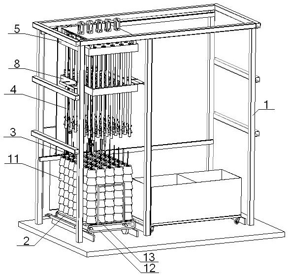
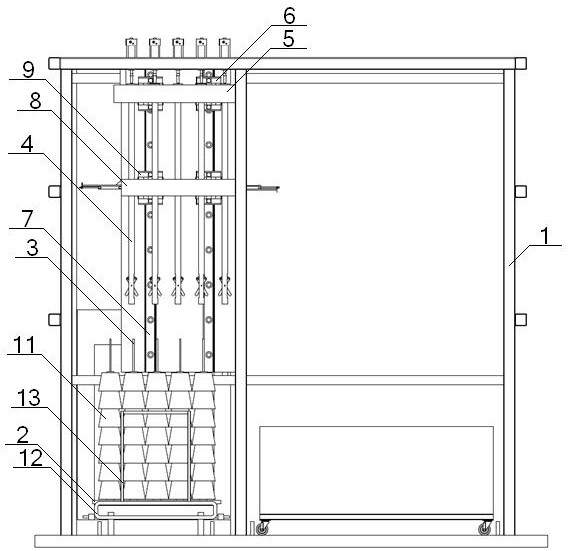
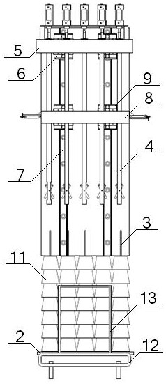
[0043] see Figure 1 to Figure 8 , a centering and positioning device for an automatic yarn unloading machine, the centering and positioning device includes a frame 1 and a bobbin frame and a centering mechanism 8 arranged on it, and the bobbin frame includes a yarn carrier plate 2 and its A plurality of yarn bobbin rods 3 vertically arranged on the top of the yarn bobbin stringing rod 3 is provided with a sleeve rod 4 corresponding to it one by one. One end of the sleeve rod 4 is connected with the moving plate 5, and the moving plate 5 passes through the The No. 1 slide block 6 is connected with the No. 1 guide rail 7 on the frame 1, and the other end of the sleeve bar 4 is provided with a yarn hanging device. The mechanism 8 includes a frame 81 and an upper splint 82 and a lower splint 83 arranged in parallel therein. The frame 81 includes a No. 1 fixed plate 811 and a No. 2 fixed plate 812 arranged in parallel, and the No. 1 fixed plate 811 and the No. 2 fixed plate 812 N...

Embodiment 2

[0045] Basic content is the same as embodiment 1, the difference is:

[0046] see Figure 5 to Figure 8 , the side of the No. 1 fixed plate 811 is provided with a No. 4 fixed plate 86 parallel to it. The No. 4 fixed plate 86 is connected with the No. 1 cylinder 84. Vertically connected, the other end of the No. 1 horizontal push rod 87 passes through the No. 1 fixing plate 811 and then vertically connects with the No. 3 plate 823 of the upper splint 82; the side of the No. 2 fixing plate 812 is provided with No. 5 Fixed plate 88, No. 5 fixed plate 88 is connected with No. 2 cylinder 85, No. 5 fixed plate 88 is vertically connected with one end of No. 2 horizontal push rod 89, and the other end of No. 2 horizontal push rod 89 passes through No. 2 fixed plate 812 Afterwards, it is vertically connected with the No. 3 plate 823 of the lower splint 83; No. 2 guide rail 814 and No. 3 guide rail 815 are arranged in parallel on the No. 3 fixed plate 813, and No. 3 slider is arranged ...

Embodiment 3

[0048] Basic content is the same as embodiment 1, the difference is:

[0049] see image 3 , Figure 4 , Figure 9 , Figure 10 , the end of the sleeve rod 4 close to the yarn bobbin rod 3 is sleeved with a bell mouth 10, the small diameter end of the bell mouth 10 is located in the sleeve rod 4, and the outer wall of the large diameter end of the bell mouth 10 is threaded with the inner wall of the sleeve rod 4 end. connect.


PUM


Abstract

A centering and positioning device for an automatic yarn unloading machine, comprising a yarn loading plate and a centering mechanism, a plurality of yarn bobbin rods are vertically arranged on the yarn loading plate, and directly above the yarn bobbin stringing rods are arranged one by one Corresponding sleeve rod, one end of the sleeve rod is connected with the moving plate, the moving plate is connected with the first guide rail through the No. 1 slider, and the other end of the sleeve rod is provided with a yarn hanging device. The upper splint, the lower splint, the frame are connected with the No. 2 slider on the No. 1 guide rail, the upper splint and the lower splint both include the No. A number of No. 3 plates are arranged in parallel between No. 2 plate and No. 3 plate. Multiple V-shaped grooves are evenly opened on the No. 3 plate. The upper splint is connected with the No. 1 cylinder, and the lower splint is connected with the No. 2 cylinder. The rod is located between the V-groove of the upper cleat and the V-groove of the lower cleat. This design not only has a high degree of automation, but also has a high centering and positioning accuracy.

Description

technical field [0001] The invention relates to the technical field of textiles, in particular to a centering and positioning device for an automatic yarn unloading machine, which is mainly suitable for improving the degree of automation of the yarn unloading machine and the centering and positioning accuracy of a yarn bobbin stringing rod and a yarn hanging mechanism. Background technique [0002] At present, most cheese dyeing enterprises are labor-intensive, and each process requires a lot of labor. With the continuous development of automation technology, people have developed various automatic auxiliary equipment for each process of cheese dyeing. In the bobbin link, in order to quickly unload the yarn, various yarn unloading machines have been developed, but the existing yarn unloading machines often have the following defects: the degree of automation is not high, a lot of human resources are wasted, and the work efficiency is low; The medium stability is low, and it ...

Claims


Application Information

Patent Timeline
Patent Type & Authority Patents(China)
IPC IPC(8): D06B23/04
CPCD06B23/04
Inventor 张成俊李冬冬吴晓左小艳刘念戴建雄刘雅昆
Owner WUHAN TEXTILE UNIV
Why Eureka
Try Eureka