Track turnout system

A track and turnout technology, applied in the field of track turnout systems, can solve the problems of switching time, limiting vehicle traffic density, increasing track complexity and failure rate, and achieving the effect of reducing adjustment time and quick adjustment

Inactive Publication Date: 2019-10-08
麻首强
View PDF5 Cites 3 Cited by
  • Summary
  • Abstract
  • Description
  • Claims
  • Application Information

AI Technical Summary

Problems solved by technology

Although the current switches can be controlled by motors and do not require manual switching, the time it takes

Method used


Image

  • Track turnout system

Examples


Embodiment

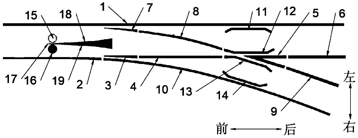
[0027] Such as figure 1 As shown, a track switch system of the present invention is characterized in that it includes: a diverter 17, a straight track, a turning track, a first guide wheel 15 and a second guide wheel 16, and the turning track is placed on the side of the straight track, One end of the turning track meets the straight track, and the splitter 17 is placed between the straight tracks, and the splitter 17 is in front of the intersection of the straight track and the turning track, and a branch center 5 is provided on the rear side of the intersection of the straight track and the turning track , the first guide wheel 15 and the second guide wheel 16 are respectively placed on both sides of the central axis of the front lower end of the rail car running on the straight track or the turning track.

[0028] The left side of the diverter 17 is provided with a first guide surface 18, the right side of the diverter 17 is provided with a second guide surface 19, and the ...


PUM


Abstract

The invention relates to a track turnout system. The track turnout system comprises a diverter, a straight-going track, a turning track, a first guide wheel and a second guide wheel; the turning trackis placed on one side of the straight-going track; one end of the turning track is intersected on the straight-going track; the diverter is positioned in front of the intersecting part of the straight-going track and the turning track; the first guide wheel and the second guide wheel are correspondingly placed on the two sides of a central axis of the lower end of the front part of a rail vehiclerunning on the straight-going track or the turning track; a first guide surface is arranged on the left side of the diverter; a second guide surface is arranged on the right side of the diverter; theright end wheel edge of the first guide wheel has a rolling guiding effect on the first guide surface to guide the rail vehicle to run along the straight-going track; the left end wheel edge of the second guide wheel has a rolling guiding effect on the second guide surface to guide the rail vehicle to be changed from the straight-going track to the turning track; and at any time, there is one andonly one guide wheel acting upon the first guide surface and the second guide surface. The track turnout system can be used for enabling the rail vehicle to simultaneously pass in two directions without changing the shape of a turnout.

Description

technical field [0001] The invention relates to the technical field of rail transit, in particular to a rail switch system. Background technique [0002] The existing track system is equipped with a switch at the branch of the track. The switch can control the direction of the wheel. If the direction of the wheel needs to be changed, the switch needs to be adjusted, which is commonly called a switch. Although the current switches can be controlled by motors and do not require manual switching, the time it takes to switch the tracks limits the density of vehicles and increases the complexity and failure rate of the tracks. Contents of the invention [0003] In order to solve the above-mentioned technical problems, the present invention provides a track switch system, so that there is no need to switch the track, and only need to make driving control on the rail vehicle, so as to solve at least one of the above-mentioned technical problems. [0004] The technical scheme tha...

Claims


Application Information

Patent Timeline
IPC IPC(8): E01B7/00
CPCE01B7/00
Inventor 麻首强
Owner 麻首强
Why Eureka
Try Eureka