Transformer mounting device

A technology for installing equipment and transformers, which is applied to earth movers/excavators, construction, etc., can solve problems such as difficult operations, low efficiency, and increase the efficiency of transformer installation, so as to improve the convenience of life, improve work reliability, and equipment The effect of simple structure

Inactive Publication Date: 2019-10-08
王军
View PDF0 Cites 1 Cited by
  • Summary
  • Abstract
  • Description
  • Claims
  • Application Information

AI Technical Summary

Problems solved by technology

[0002] The installation process of the transformer is mainly to dig out a tunnel on the ground to place the utility pole, and then put the utility pole into the tunnel for stable and fixed installation. Generally, the transformer needs to be introduced into the ground pole to realize the insulation function. Generally, the part of the transformer that is introduced into the ground pole , it is necessary to dig trenches on the ground, and place metals that can be used for electrical conduction into the trenches. During this process, trench excavation is difficult and inefficient, which greatly reduces the working efficiency of the equipment, and Since the installation of transformers is not limited to places where the ground is flat, when installing transformers in some mountainous areas or places with uneven ground, due to the long distance, it is difficult to dig trenches for equipment, which greatly hinders the operation of transformers. Efficient installation, and to a large extent, increased the efficiency of transformer installation, and it is not convenient for efficient erection of wires, so that people in remote mountainous areas cannot use stable civilian electricity

Method used


Image

  • Transformer mounting device
  • Transformer mounting device
  • Transformer mounting device

Examples


Embodiment Construction

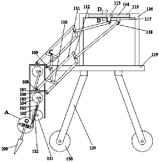
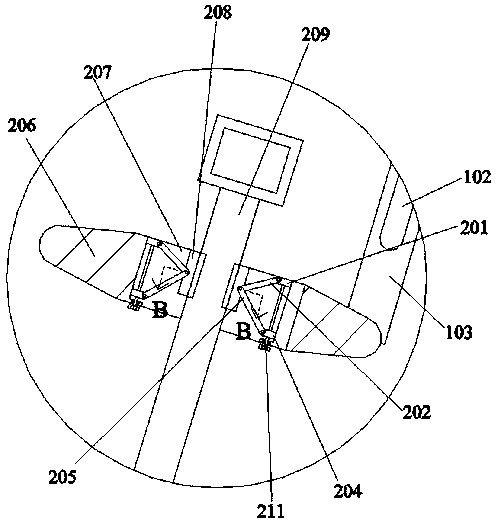
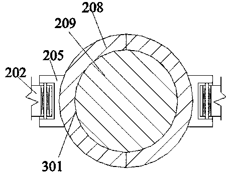
[0023] Such as Figure 1-Figure 5 As shown, the present invention is described in detail. For the convenience of description, the orientations mentioned below are now stipulated as follows: figure 1 The up, down, left, right, front and back directions of the projection relationship are consistent. A transformer installation device of the present invention includes a platform plate 119, and a symmetrical bottom bar 129 is fixed on the lower end surface of the platform plate 119. The inner rotation of the bottom bar 129 is also set. There is a driving wheel 130 driven by a motor, and a ditching device for ditching is provided on the upper surface of the platform plate 119, so that the ditching device is used to carry out an efficient ditching process.

[0024] Beneficially, wherein, the ditching device includes an excavation assembly that is arranged on the left side of the platform plate 119 and uses a rotating manner to excavate the soil efficiently, and the right side of the ...


PUM


Abstract

The invention discloses a transformer mounting device. The device comprises a platform plate, symmetric bottom rods are fixedly arranged on the lower end face of the platform plate, driving wheels driven through a motor are rotatably arranged in the bottom rods, and a ditching device used for ditching is arranged on the upper end face of the platform plate. The device is simple in structure, the motor is adopted for directly driving the wheels to rotate, the device can be convenient to carry, and can conveniently work on the uneven ground and the mountain area, a series of connecting rod typeexcavating structures are used, the device can efficiently carry out ditching work, equipment work reliability is greatly improved, a transformer can be efficiently mounted in some remote areas, transmission of civil electricity is facilitated, and the life convenience degree of the person is improved.

Description

technical field [0001] The invention relates to the technical field of transformer installation equipment, in particular to a transformer installation equipment. Background technique [0002] The installation process of the transformer is mainly to dig out a tunnel on the ground to place the utility pole, and then put the utility pole into the tunnel for stable and fixed installation. Generally, the transformer needs to be introduced into the ground pole to realize the insulation function. Generally, the part of the transformer that is introduced into the ground pole , it is necessary to dig trenches on the ground, and place metals that can be used for electrical conduction into the trenches. During this process, trench excavation is difficult and inefficient, which greatly reduces the working efficiency of the equipment, and Since the installation of transformers is not limited to places where the ground is flat, when installing transformers in some mountainous areas or pla...

Claims


Application Information

Patent Timeline
IPC IPC(8): E02F5/02
CPCE02F5/027
Inventor 王军
Owner 王军
Why Eureka
Try Eureka