Reinforcing steel bar bending machine applied to engineering construction

A bending machine and steel bar technology, applied in the field of steel bar bending machines, can solve problems such as large impact of punches, cracking, and strength damage of steel bar bending, so as to improve bending efficiency, reduce adverse effects, and high bending efficiency Effect

Active Publication Date: 2019-10-11
闽清紫扬信息技术有限公司
View PDF8 Cites 2 Cited by
  • Summary
  • Abstract
  • Description
  • Claims
  • Application Information

AI Technical Summary

Problems solved by technology

Moreover, in some connection occasions, it is necessary to bend the steel bars to adapt to different bending angles. The current steel bar bending machines generally use stamping and other methods for bending. Due to the great impact force, it is easy to cause great damage to the strength of the bending part of the steel bar. On the other hand, it is difficult to accurately grasp the bending angle of the steel bar in the punching and bending method, and it is difficult to perform the bending operation as required. , the way of punching and bending has a great influence on the punch, and it is prone to cracking, which has a great impact on the personal safety of the operator.

Method used


Image

  • Reinforcing steel bar bending machine applied to engineering construction
  • Reinforcing steel bar bending machine applied to engineering construction
  • Reinforcing steel bar bending machine applied to engineering construction

Examples


Embodiment Construction

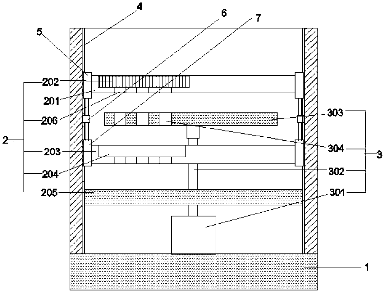
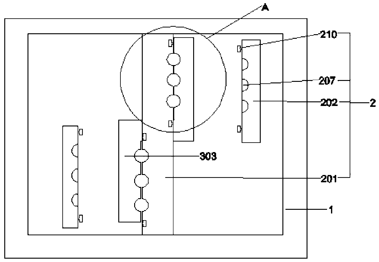
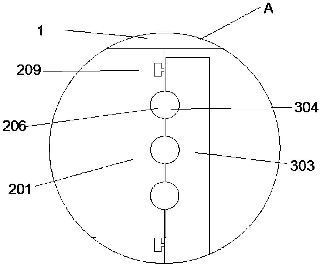
[0025] See Figure 1~6 In an embodiment of the present invention, a steel bar bending machine for engineering construction, the steel bar bending machine includes a base 1, a support base, an axial bending mechanism 2 and a radial bending mechanism 3, wherein the base 1 The upper end is provided with a support base extending vertically upwards, the support base is provided with the axial bending mechanism and the radial bending mechanism, characterized in that the axial bending mechanism is located on the axis of the steel bar to be bent To both ends to apply a vertical axial bending force to the steel bar; the radial bending mechanism initially applies a bending force in the radial direction of the steel bar; it also includes a controller that controls the axial top The bending force and the bending displacement of the bending mechanism 2 and the radial bending mechanism 3, and when the steel bar is initially bent, the controller controls the radial bending mechanism to bend w...


PUM


Abstract

The invention discloses a reinforcing steel bar bending machine applied to engineering construction. Through simultaneous bending of an axial push bending mechanism and a radial bending mechanism, themachine disclosed by the invention can bend a reinforcing steel bar in a relatively gentle manner, and the problem in damage of an internal structure of the reinforcing steel bar caused by impact bending does not take place. Meanwhile, during initial bending of the reinforcing steel bar with the machine disclosed by the invention, a controller controls the radial bending mechanism to bend at maximum bending force; and with running of a bending action of the reinforcing steel bar, bending force of the axial push bending mechanism gradually increases and bending force of the radial bending mechanism gradually decreases, so the reinforcing steel bar can be bent in an optimal, effort-saving and gentle manner, and bad influences on bent parts of the reinforcing steel bar can be reduced. The machine disclosed by the invention has the beneficial effects that a movable fixation disk is disposed and in joggled joint with an upper push bending disk and a lower push bending disk, so the to-be-bent reinforcing steel bar can be easily fixed and can also be taken out easily after bending, and bending efficiency is high; and a plurality of reinforcing steel bars can be bent at the same time, andthe bending efficiency is high.

Description

Technical field [0001] The invention relates to the technical field of building supplies, in particular to a steel bar bending machine for engineering construction. Background technique [0002] At present, in the field of construction, the application of steel bars is increasing. Moreover, in some connection occasions, the steel bar needs to be bent to adapt to different bending angles. The current steel bar bending machine generally uses stamping and other methods to bend. This bending method, on the one hand, is Due to the extreme impact force, the bending strength of the steel bar is easily damaged. On the other hand, the bending method is difficult to accurately grasp the bending angle of the steel bar, and it is difficult to perform the bending operation as needed. , The punching and bending method has a greater impact on the punch, prone to cracking problems, and has a greater impact on the personal safety of the operators. Summary of the invention [0003] The purpose of...

Claims


Application Information

Patent Timeline
Patent Type & Authority Applications(China)
IPC IPC(8): B21F1/00
CPCB21F1/00
Inventor 郭玉静
Owner 闽清紫扬信息技术有限公司
Why Eureka
Try Eureka