A wind power blade girder laying system and control method thereof

A technology for wind power blades and girders, which is applied in the field of wind power blade girder laying system and its control, and can solve problems such as difficulty in application, difficulty in ensuring accuracy of manual laying, and low efficiency

Active Publication Date: 2020-06-23
CHANGZHOU HONGFA ZONGHENG ADVANCED MATERIAL TECH
View PDF8 Cites 0 Cited by
  • Summary
  • Abstract
  • Description
  • Claims
  • Application Information

AI Technical Summary

Problems solved by technology

[0003] The production of the main girder of wind power blades will be vacuum infused and hoisted after the infusion is completed after the coil is laid. In the prior art, the coil is laid manually, and the leveling and offset of the coil are performed manually. Correction is very inefficient, and due to the inconsistency of the beam mold, the accuracy of manual laying is difficult to guarantee, and the general mechanical walking structure (such as suspended gantry structure, ground rail mobile structure) is also difficult to apply

Method used


Image

  • A wind power blade girder laying system and control method thereof
  • A wind power blade girder laying system and control method thereof
  • A wind power blade girder laying system and control method thereof

Examples


Embodiment 1

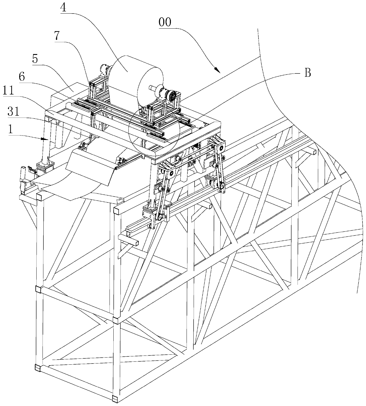
[0048] Example 1: A wind turbine blade girder laying system, such as image 3 As shown, it includes a mobile trolley 1, which moves along the track in the extension direction of the beam mold 00 for coil laying; a two-step correction device to ensure that the color yarn spacing between each layer of the coil along the extension direction of the beam mold 00 is consistent; The unwinding device 4 is used for the constant tension unwinding of the coil, which can be realized by coaxially connecting the magnetic powder brake with the air expansion shaft; the PLC controller 5 is used to control the moving trolley 1, the two-step correction device and the unwinding device 4 Actions. The mobile trolley 1 is slidably connected to a first base 6 in a direction perpendicular to the laying direction of the coils, and a second base 7 is slidably connected to the first base 6, and the unwinding device 4 is installed on the second base 7; The movement of 6 is used to adjust the distance betwe...

Embodiment 2

[0062] Embodiment 2: A control method of a wind turbine blade girder laying system, which is different from Embodiment 1 in that: Figure 3 to Figure 7 Shown, including:

[0063] S1: The mobile car 1 is erected on the rail of the beam mold 00, and one end of the coil is fixed to one end of the beam mold 00;

[0064] S2: The colored yarn sensor 21 tracks the colored yarn on the beam mold 00. After the colored yarn sensor 21 detects the colored yarn of the coil, it is transmitted to the PLC controller 5. The PLC controller 5 controls the action of the second actuator 22 to adjust the first The base 6 moves, and the moving distance is the color yarn spacing between each layer of coil;

[0065] S3: The mobile trolley 1 moves to the other end along the rail of the beam mold 00 under power to complete the laying of the first layer of coiled material. The power of the mobile trolley 1 is provided by the drive unit 13, and the coiled material is laid under constant tension. In roll form, t...


PUM

PropertyMeasurementUnit
lengthaaaaaaaaaa

Abstract

The invention discloses a wind power blade girder laying system and a control method thereof, and belongs to the field of wind power blade production equipment. The laying system has the advantages ofbeing capable of realizing automatic online laying of a coiled material on a girder mold, the technical scheme is characterized by comprising a moving trolley, a two-step deviation rectifying device,an unreeling device and a PLC, wherein the moving trolley moves along a rail in the extending direction of the girder mold and is used for laying the coiled material; the two-step deviation rectifying device guarantees that the distance between each layer of the coiled material in the extending direction of the girder mold is consistent; the unreeling device is used for constant-tension unreelingof the coiled material; the PLC is used for controlling the movement of the moving trolley, the two-step deviation rectifying device and the unreeling device; and the moving trolley is slidably connected with a first base in a direction perpendicular to the laying direction of the coiled material, the first base is slidably connected with a second base, and the unwinding device is arranged on thesecond base. The wind power blade girder laying system is suitable for laying wind power blade girders.

Description

Technical field [0001] The invention relates to a laying system, in particular to a wind power blade girder laying system and a control method thereof. Background technique [0002] At present, the main beam of wind turbine blades needs to be spread on the beam mold 00. The structure of the beam mold 00 is as follows: figure 1 with figure 2 As shown, it has the following characteristics: (1) The beam mold 00 presents an upper arch or a lower arch in the length direction, the total length of the beam mold 00 is 61.5m, the highest point is 2.83m, and the lowest point is 0.88m; (2), roll The laying area 001 of the material is concave in the beam mold 00; (3) The left and right sides of the beam mold 00 at the same length have a height difference relative to the horizontal plane, that is, the FRP mold 002 is spatially distorted along the length, and is twisted relative to the horizontal plane The angle changes from -3.5°-11.2°; (4) The left and right sides of the mold support struct...

Claims


Application Information

Patent Timeline
Patent Type & Authority Patents(China)
IPC IPC(8): B29C70/38B29C70/54B29L31/08
CPCB29C70/386B29C70/54B29L2031/085
Inventor 谈昆伦季小强
Owner CHANGZHOU HONGFA ZONGHENG ADVANCED MATERIAL TECH
Why Eureka
Try Eureka