Running device of bionic foot robot

A technology of robots and walking devices, applied in the field of robots, can solve the problems of high ground flatness requirements, failure to maintain crawlers, wear and tear, etc., and achieve the effects of good structural performance, simple structure, and convenient operation

Inactive Publication Date: 2019-10-11
NANJING NIEBO INTERNET OF THINGS TECH CO LTD
View PDF8 Cites 6 Cited by
  • Summary
  • Abstract
  • Description
  • Claims
  • Application Information

AI Technical Summary

Problems solved by technology

[0003] The walking devices in the prior art generally can only walk on flat ground. When encountering obstacles, other paths must be selected. At the same time, a stable state of the ...

Method used


Image

  • Running device of bionic foot robot
  • Running device of bionic foot robot
  • Running device of bionic foot robot

Examples


Embodiment 1

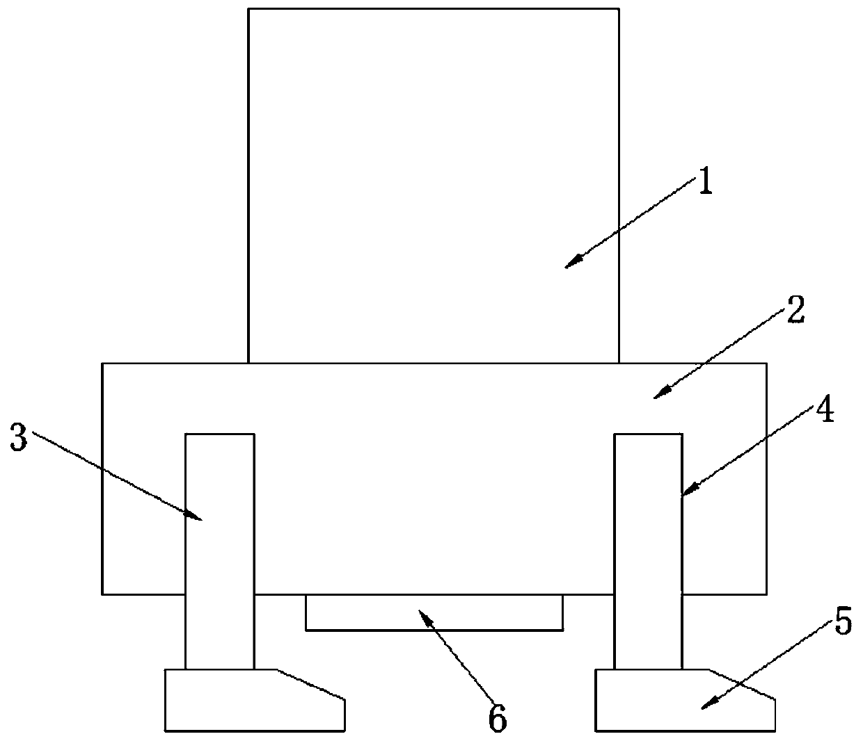
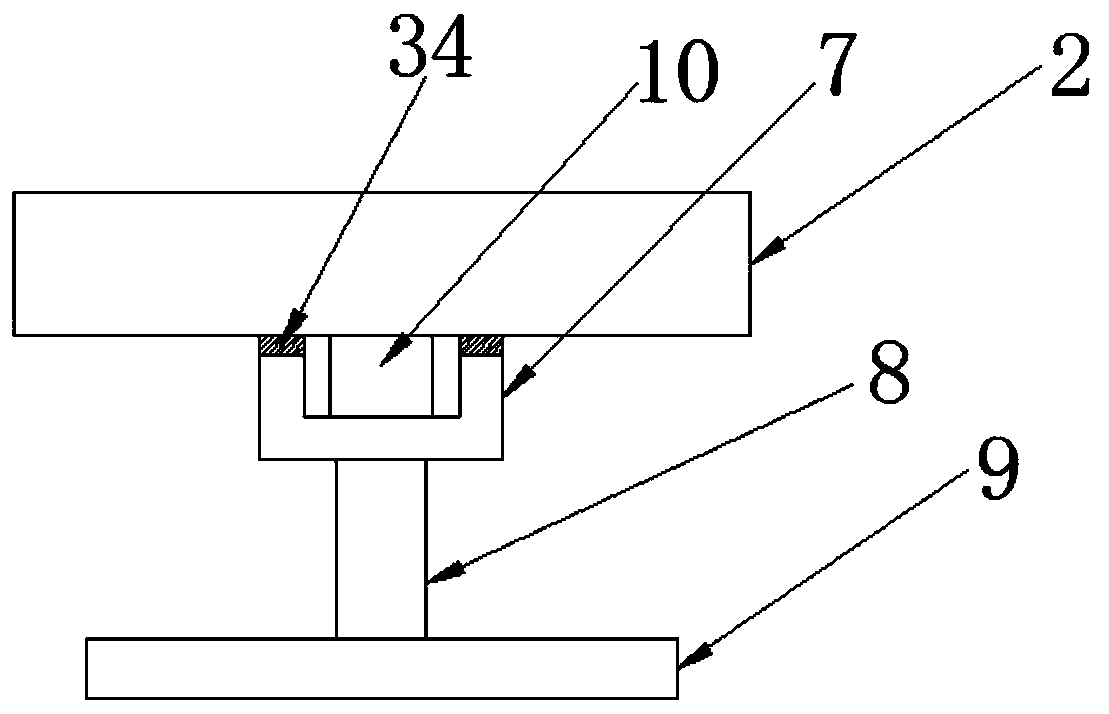
[0026] Embodiment one, such as Figure 1-2 As shown, the walking device of a kind of bionic legged robot according to the embodiment of the present invention comprises a robot body 1, the lower end of the robot body 1 is provided with a walking device 2, and both sides of the walking device 2 are provided with a support bar-3 and a support The lower ends of rod two 4, support rod one 3 and support rod two 4 are all provided with support blocks 5, and in order to increase the friction between the support block 5 and the ground, the inventor evenly provides some sawtooth 33 at the lower end of support block 5, To make the walking device 2 more stable during the movement, the bottom of the walking device 2 is provided with a steering device 6, wherein the steering device 6 includes a support plate 7, and both sides of the upper end of the support plate 7 are connected to the lower end of the walking device 2 , the lower end of the support plate 7 is provided with a hydraulic cyli...

Embodiment 2

[0027] Embodiment two, the structure and effect of the walking device 2 are specifically described below.

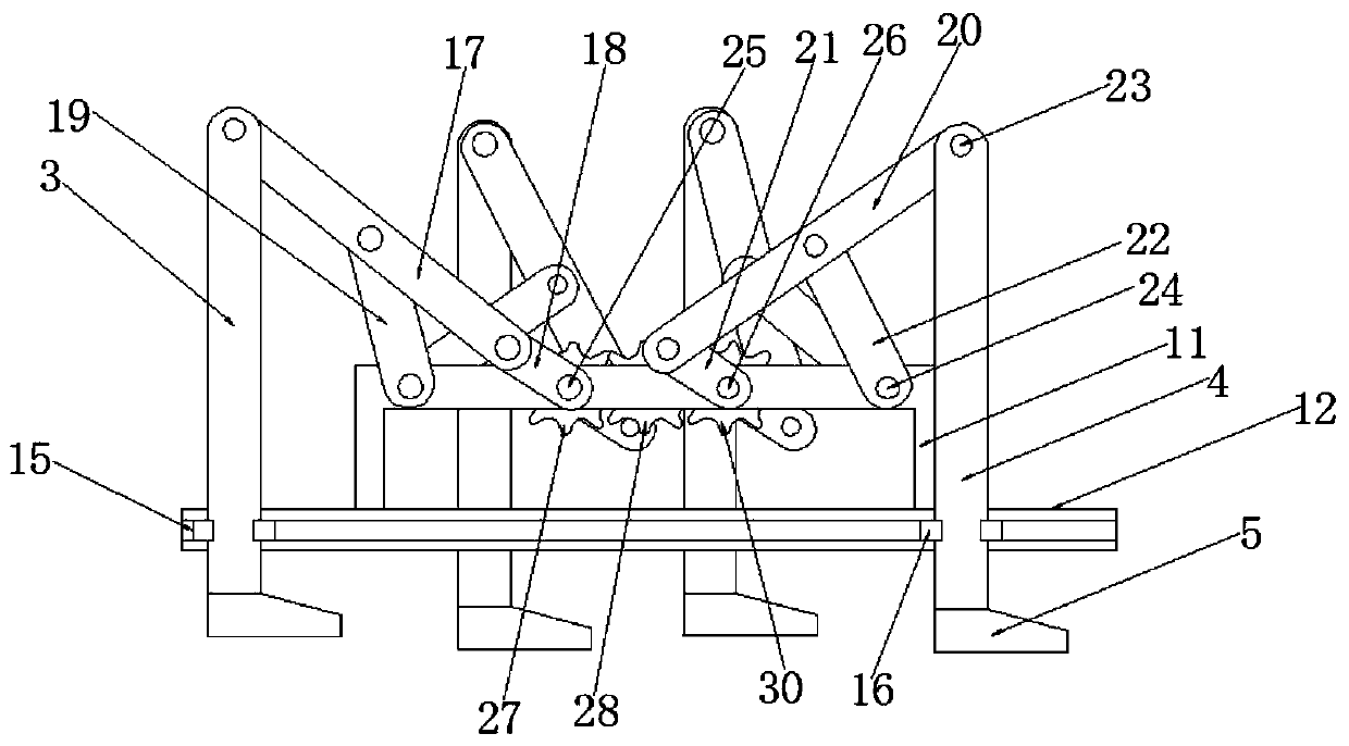
[0028] like image 3 Shown, walking device 2 comprises fixed frame 11, for the design of fixed frame shape, generally adopts the design of cuboid, and, the upper end of fixed frame 11 is connected with robot body 1, and the lower end of fixed frame 11 is connected with steering gear 6. The output end of the rotating motor 10 is connected. The function of the fixed frame 11 is mainly to play a supporting role. It should be noted here that the walking device 2 has a symmetrical structure, and the structures on both sides of the fixed frame 11 are the same. Here, the focus is on the fixed The concrete structure of frame 11 one side, the lower end side of fixed frame 11 is provided with chute 12, and the inner side of chute 12 is provided with slide block one 13, and the inside other side of chute 12 is provided with slide block two 14, And, slide block one 13 and slide blo...

Embodiment 3

[0031] Embodiment 3, the structure and function of the rotating mechanism will be specifically introduced below.

[0032] like Figure 5 As shown, the rotating mechanism includes gear one 27, gear two 28, gear three 29 and gear four 30, and gear one 27 and gear two 28 mesh with each other, gear three 29 and gear four 30 mesh with each other, and gear one 27 is sleeved on On movable shaft one 25, gear four 30 is set on movable shaft two 26, and one side of gear two 28 is provided with motor one 31, and one side of gear three 29 is provided with motor two 32, and, motor one 31 and motor two 32 are positioned at the inner both sides of fixed frame 11 respectively, by the rotation of two groups of motors, can realize the rotation of gear one 27 and gear four 30, and then drive the motion of movable shaft one 25 and movable shaft two 26.

[0033] In order to facilitate the understanding of the above-mentioned technical solution of the present invention, the working principle or op...


PUM


Abstract

The invention discloses a running device of a bionic foot robot. The running device of the bionic foot robot comprises a robot body; a running device is arranged at the lower end of the robot body; asupporting rod I and a supporting rod II are arranged on the two sides of the running device; supporting blocks are arranged at the lower end of the supporting rod I and the lower end of the supporting rod II; a steering device is arranged at the bottom of the running device, wherein the steering device comprises a supporting plate; and moreover, the two sides of the upper end of the supporting plate are connected with the lower end of the running device; a hydraulic cylinder is arranged at the lower end of the supporting plate; an output end of the hydraulic cylinder is connected with the upper end of a bottom plate; a rotating motor is arranged in the middle position of the upper end of the supporting plate; an output shaft of the rotating motor is connected with the lower end of the running device; the running device comprises a fixing frame; the upper end of the fixing frame is connected with the robot body; the lower end of the fixing frame is connected with the steering device; the running device is of a symmetric structure; and moreover, the structures of the two sides of the fixing frame are as same as each other; a slide groove is formed in one side of the lower end of thefixing frame; a slide block I is arranged on one side of the interior of the slide groove; and a slide block II is arranged on the other side of the interior of the slide groove.

Description

technical field [0001] The invention relates to the field of robots, in particular to a shape walking device of a bionic legged robot. Background technique [0002] At present, from its definition, a robot is a mechanical device used to replace human beings for some heavy physical work. The walking mechanism of the robot is an important executive component of the walking robot. On the one hand, the walking mechanism supports the body of the robot, The arm and hand must have sufficient rigidity and stability; on the other hand, it is also necessary to realize the movement of the robot in a wider space according to the requirements of the task. [0003] The walking devices in the prior art generally can only walk on flat ground. When encountering obstacles, other paths must be selected. At the same time, a stable state of the track cannot be maintained, and the wear and tear are serious. They walk on wheels, but they have high requirements for the flatness of the ground, wh...

Claims


Application Information

Patent Timeline
IPC IPC(8): B62D57/032
CPCB62D57/032
Inventor 朱小冯大军马泽朋
Owner NANJING NIEBO INTERNET OF THINGS TECH CO LTD
Why Eureka
Try Eureka