Tile connecting device, tiled roof and mounting method of tile connecting device

A technology of connection device and installation method, which is applied to roofs, roofs, and roof coverings using tiles/slate tiles, and can solve the problem of short service life of adhesive materials affecting the life of tile roofs and the sealing performance of upper and lower tiles Poor, unable to achieve sealing and self-balancing of wind loads, etc., to reduce the risk of being overturned by the wind, improve the wind resistance and light weight

Pending Publication Date: 2019-10-11
BEIJING HANERGY PV TECH CO LTD
View PDF0 Cites 0 Cited by
  • Summary
  • Abstract
  • Description
  • Claims
  • Application Information

AI Technical Summary

Problems solved by technology

[0007] The object of the present invention is to provide a tile connecting device, which forms a fast connection between the upper tile and the lower tile by using the first connecting piece, the second connecting piece, a plurality of locking parts and connecting wires, so as to solve the problem of In the prior art, the tiles are glued to increase the weight of the roof, which increases the load on the beams and columns, and the technical problems that the service life of the adhesive material is short affects the life of the tile roof; by setting the second layer between the upper and lower tiles The elastic connection of the first sealing part solves the technical problem of poor sealing performance between the upper tile and the lower tile. At the same time, the first sealing part and the connecting line work together to solve the problem that the tile roof in the prior art cannot achieve sealing and wind load Self-balancing, resulting in the technical problem that the wind will overturn the tiles and cause secondary damage

Method used


Image

  • Tile connecting device, tiled roof and mounting method of tile connecting device
  • Tile connecting device, tiled roof and mounting method of tile connecting device
  • Tile connecting device, tiled roof and mounting method of tile connecting device

Examples


Embodiment 1

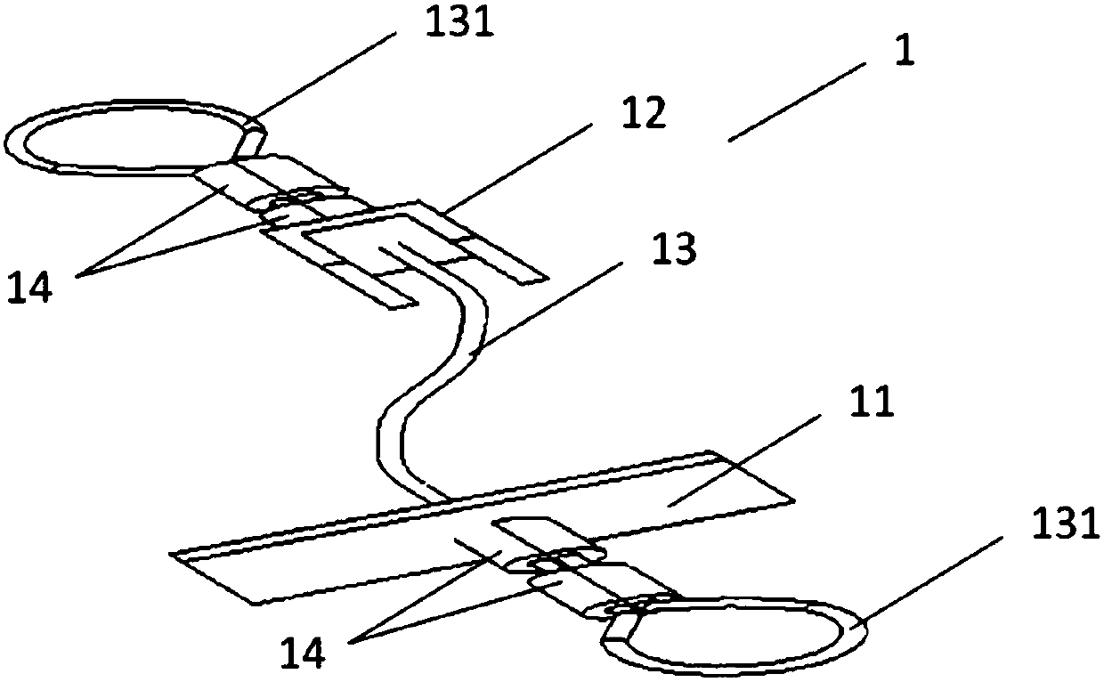
[0059] figure 1 It is a schematic structural diagram of a tile connecting device provided in the first embodiment of the present invention.

[0060] Please refer to figure 1 , This embodiment provides a tile connecting device, including: a first connecting piece 11, a second connecting piece 12, a connecting wire 13, and a plurality of locking components 14.

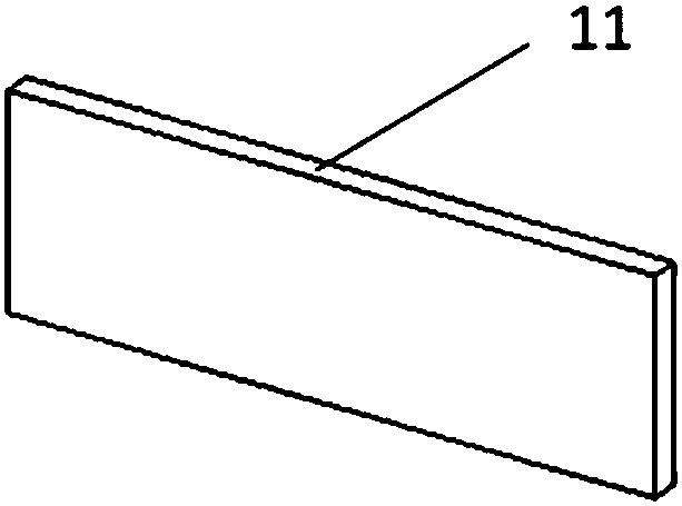
[0061] The first connecting member 11 has a plate-like structure and is used to connect the two tiles 2 of the lower layer. Specifically, the first connecting member 11 is located at the joint of the two adjacent tiles 2 of the lower layer to realize the connection of the two adjacent tiles 2 of the lower layer.

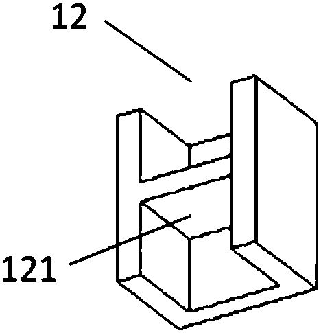
[0062] The second connecting member 12 is a groove-shaped structure, and is arranged opposite to the first connecting member 1 for connecting the two upper tiles 2.

[0063] One end of the connecting wire 13 extends out of the first connecting member 11 and the other end extends out of the second connecting member 12. ...

Embodiment 2

[0095] Image 6 It is a front view of a tile roof provided in the second embodiment of the present invention.

[0096] Figure 7 It is a first-direction perspective view of a tile roof provided in the second embodiment of the present invention.

[0097] Picture 8 It is a second-direction perspective view of a tile roof provided in the third embodiment of the present invention.

[0098] Please refer to Image 6 , Figure 7 , Picture 8 This embodiment provides a tile roof, a tile roof, including the tile connecting device 1 described in Embodiment 1, and further includes: a plurality of tiles 2.

[0099] One end of the tile connecting device 1 is connected with the two upper tiles 2 and the other end is connected with the two lower tiles 2 for connecting multiple tiles 2 into a whole to increase the load bearing area of ​​the tile roof , Thereby increasing the wind resistance of the tile roof.

[0100] Wherein, the first connector 11 of the tile connecting device 1 is arranged under th...

Embodiment 3

[0143] Picture 9 It is a schematic diagram of the installation of the tile connecting device provided in the third embodiment of the present invention.

[0144] Picture 10 It is a method flowchart of the installation method of the tile connection device provided in the third embodiment of the present invention.

[0145] Please refer to Picture 9 , Picture 10 This embodiment provides a method for installing the tile connecting device 1 in the first embodiment to form the tile roof in the second embodiment, including:

[0146] S100, bending one end of the connecting wire 13 into a ring shape, and locking it with the locking member 14 to form a pull ring 131, and the other end of the connecting wire 13 is a free end.

[0147] Specifically, pressure is applied to the locking member 14 to deform it, so that one end of the connecting wire 13 is locked to form a pull ring 131.

[0148] S200: Pass the free end of the connecting wire 13 through the first connecting piece 11.

[0149] S300: Pa...


PUM


Abstract

The invention discloses a tile connecting device, and belongs to the technical field of buildings. The device comprises a first connecting part (11) which is of a plate-shaped structure, and used forconnecting two tiles (2) on the lower layer, a second connecting part (12) which is of a groove-shaped structure, is opposite to the first connecting part (11) and is used for connecting two tiles (2)on the upper layer, a connecting line (13) and locking parts (14), wherein one end of the connecting line extends out of the first connecting part (11), and the other end of the connecting line extends out of the second connecting part (12); and the locking parts (14) are arranged on the two ends of the connecting line (13) and used for locking the connecting line (13) so as to lock the first connecting part (11) and the second connecting part (12) to preset positions, and the connecting line is kept tensioned at the mounting position. The tile connecting device is small in weight, long in service life, good in seal property, high in wind resistance capacity, meanwhile, easy to mount, easy to operate and capable of greatly improving the tiled roof mounting efficiency.

Description

Technical field [0001] The invention relates to the field of construction technology, in particular to a tile connection device, a tile roof and an installation method thereof. Background technique [0002] In the prior art, tile roofs are mostly tiled or connected by adhesives to fix the tile connection to the roof structure. However, this connection method has the following defects: [0003] 1. The tile is fixed on the roof with an adhesive, which increases the weight of the roof, which increases the load on the beams and columns, and the service life of the adhesive material is generally shorter, thereby affecting the service life of the tile roof. [0004] 2. When the tiles are flat on the roof, the sealing performance is poor, the external environment is bad or the range of changes in a short period of time is large, the independent enhancement and adaptation of the sealing function cannot be realized, and the self-balance of the sealing and wind load cannot be realized, result...

Claims


Application Information

Patent Timeline
Patent Type & Authority Applications(China)
IPC IPC(8): E04D1/34
CPCE04D1/34E04D1/2916
Inventor 高廷飞杨世忠李秀祖高恺冯慧慧
Owner BEIJING HANERGY PV TECH CO LTD
Why Eureka
Try Eureka