

Air separation oxygen generating device for energy accumulating and releasing
A technology of air separation and oxygen production equipment, which is applied in the direction of specific gas purification/separation, oxygen preparation, steam engine equipment, etc., which can solve problems such as limiting the scope of use, and achieve the effect of improving economic benefits
Pending Publication Date: 2019-10-11
杭州杭氧化医工程有限公司
View PDF0 Cites 14 Cited by
- Summary
- Abstract
- Description
- Claims
- Application Information
AI Technical Summary
Problems solved by technology
However, specific conditions of use limit its scope of use. In order to seek better energy integration, it is urgent to find a more efficient and economical solution within the system.
Method used
View moreImage
Smart ImageViewing Examples

Examples
Embodiment
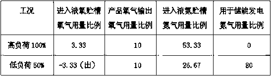
[0032] For the convenience of understanding the functions of the present invention, it is assumed that the air components only contain oxygen and nitrogen, and the contents are respectively 20% of oxygen and 80% of nitrogen. Regardless of the amount of regeneration gas, it is assumed that the high and low loads are 100% and 50% respectively, for power generation and products. The ratio of oxygen or nitrogen consumption to the air consumption in the whole stage is shown in the table below:
[0033] Comparison table of oxygen and nitrogen dosage under two working conditions
[0034]
Login to View More PUM
 Abstract
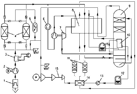
The invention discloses an air separation oxygen generating device for energy accumulating and releasing. The device is characterized in that an air separation oxygen generating device and a nitrogenexpansion power generating device are included, oxygen products are stably output in the long term through an air separation variable loading technology and a liquid nitrogen energy accumulating technology, and electricity is output at a peak power consumption period. The device has the advantages that the whole process continuous operating of an energy accumulating device (air separation device)is achieved to effectively reduce debugging consumption and faulty risks due to frequent on and off of equipment, high-value oxygen products can be obtained while an energy accumulating power generating function can be achieved, and the technology is an efficient and economical energy accumulating technology.
Description
technical field [0001] The invention relates to the technical field of compressed air energy storage, in particular to a liquefied air energy storage technology combined with air separation, which is suitable for energy storage to generate electricity and output oxygen products. Background technique [0002] The global energy supply is facing many challenges, and it is more urgent to increase the output of renewable energy power generation. At present, as an attractive energy storage technology, liquefied air energy storage technology (LAES) has high energy density and is easy to store, which can effectively solve the problem of instability of renewable energy power generation. Air liquefaction energy storage technology uses air as the carrier. Due to the limitation of the overall cycle efficiency of the system and considering factors such as peak and valley electricity price differences, there is a problem of low practical value. [0003] In practical applications, the liq...
Claims
Login to View More Application Information
Patent Timeline
 IPC IPC(8): F25J3/04C01B13/02F01K25/10
CPCF25J3/04018F25J3/04024C01B13/0259F01K25/10C01B2210/0046C01B2210/0014F25J3/04084F25J3/04181F25J3/04218F25J3/04296F25J3/04412F25J3/04496F25J3/04581F25J2205/24F25J2245/42
Inventor苏苗印
Owner杭州杭氧化医工程有限公司