Wide-beam dielectric resonator antenna based on embedded metal column

A technology of dielectric resonator and metal column, applied in resonant antennas, antennas, electrical short antennas, etc., can solve the problems of limited application range, and achieve the effects of easy excitation, wide bandwidth, and easy resonance.

Active Publication Date: 2019-10-11
XIDIAN UNIV
View PDF9 Cites 2 Cited by
  • Summary
  • Abstract
  • Description
  • Claims
  • Application Information

AI Technical Summary

Problems solved by technology

However, the beamwidth of this antenna can reach about ±50°, and the application range is limited

Method used


Image

  • Wide-beam dielectric resonator antenna based on embedded metal column
  • Wide-beam dielectric resonator antenna based on embedded metal column
  • Wide-beam dielectric resonator antenna based on embedded metal column

Examples


Embodiment 1

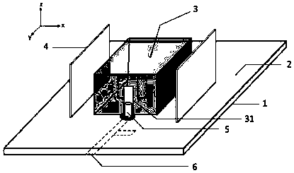
[0025] refer to figure 1 , figure 2 , image 3 with Figure 4

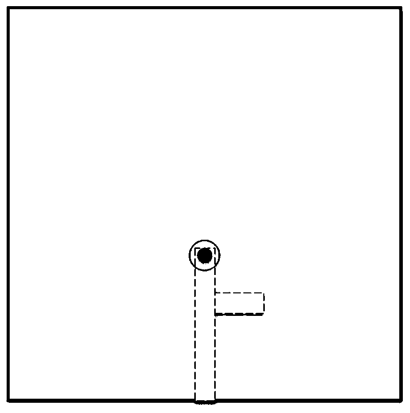
[0026] A wide-beam dielectric resonator antenna based on embedded metal pillars, including a dielectric substrate 1, a metal floor 2, a cuboid dielectric block 3, two metal plates 4 with the same structure, a metal probe 5 and a metal microstrip line 6; The metal floor 2 and the metal microstrip line 6 are printed on the upper surface and the lower surface of the dielectric substrate 1 respectively. One end of the metal microstrip line 6 is connected to the metal probe 5, and the other end extends to the bottom of the dielectric substrate 1. Edge; the cuboid dielectric block 3 also includes a metal sheet 31 and three metal columns 32 of the same structure, the cuboid dielectric block 3 is located on the upper surface of the metal floor 2, and the metal sheet 31 is printed on the cuboid dielectric block 3 The side connected to the metal probe 5, and connected to the metal probe 5; the three metal pillars 32 of...

Embodiment 2

[0035] The distance between the three metal pillars 32 of the same structure is represented as S, wherein S is twice the diameter of the metal pillars; the height of the rectangular parallelepiped dielectric block 3 is represented as h, wherein the metal pillars 32 The height is 0.4h ~ 0.6h. The height of the metal post 32 of the present invention is 0.4h.

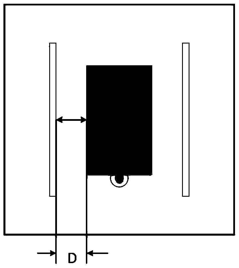
[0036] The two identical metal plates 4 are respectively perpendicular to the XOY plane and parallel to the long sides of the cuboid dielectric block 3 .

[0037] The distance between the two identical metal plates 4 and the rectangular parallelepiped dielectric block 3 is denoted as D, where D is 2.5 mm to 6 mm; the length and height of the two identical metallic plates 4 are not less than the rectangular parallelepiped dielectric block 3 length and height. The distance D between the metal plate 4 of the present invention and the cuboid dielectric block 3 is 2.5mm.

[0038] The metal sheet 31 is printed on the center o...

Embodiment 3

[0041] The distance between the three metal pillars 32 of the same structure is represented as S, wherein S is twice the diameter of the metal pillars; the height of the rectangular parallelepiped dielectric block 3 is represented as h, wherein the metal pillars 32 The height is 0.4h ~ 0.6h. The height of the metal post 32 of the present invention is 0.6h.

[0042] The two identical metal plates 4 are respectively perpendicular to the XOY plane and parallel to the long sides of the cuboid dielectric block 3 .

[0043] The distance between the two identical metal plates 4 and the rectangular parallelepiped dielectric block 3 is denoted as D, wherein D is 2.5 mm to 6 mm; the length and height of the two identical metallic plates 4 are not less than the rectangular parallelepiped dielectric block 3 length and height. The distance D between the metal plate 4 of the present invention and the cuboid dielectric block 3 is 6 mm.

[0044] The metal sheet 31 is printed on the center of...


PUM

PropertyMeasurementUnit
relative permittivityaaaaaaaaaa

Abstract

The invention provides a wide-beam dielectric resonator antenna based on an embedded metal column; the wide-beam dielectric resonator antenna comprises a dielectric substrate, a metal floor, a cuboiddielectric block, two metal plates of the same structure, a metal probe and a metal micro-strip line; the metal floor and the metal micro-strip line are printed on the upper surface and the lower surface of the dielectric substrate respectively; the cuboid dielectric block further comprises a metal sheet and three metal columns of the same structure, and the cuboid dielectric block is positioned on the upper surface of the metal floor; the metal sheet is printed on the side surface, connected with the metal probe, of the cuboid dielectric block, and is connected with the metal probe; the threemetal columns of the same structure are arranged in the center of the cuboid dielectric block in the X-axis direction and are perpendicular to the metal floor; and the two metal plates of the same structure are arranged on the two sides of the long edge of the cuboid dielectric block respectively, and are combined with the three metal columns of the same structure for widening the beam width. Thewide-beam dielectric resonator antenna is suitable for application occasions of wide-beam antennas.

Description

technical field [0001] The invention belongs to the technical field of antennas, in particular to a wide-beam dielectric resonator antenna embedded with metal posts. Suitable for wide beam antenna applications. Background technique [0002] In recent years, the application and research of dielectric resonator antennas have received more and more attention, especially in the field of microwave radio frequency. In 1939, Richtinger theoretically proved for the first time that dielectric spheres and dielectric rings can play the role of microwave resonators, and proposed the concept of dielectric resonators. As a resonant antenna, a dielectric resonator is composed of low-loss microwave materials. The higher the relative permittivity, the larger the quality factor and the smaller the bandwidth. Usually, in order to obtain a wider bandwidth, a dielectric material with a relative permittivity of about 10 is generally selected to make a dielectric resonator antenna. Because the ...

Claims


Application Information

Patent Timeline
Patent Type & Authority Applications(China)
IPC IPC(8): H01Q1/36H01Q1/48H01Q1/50H01Q9/04
CPCH01Q1/36H01Q1/48H01Q1/50H01Q9/0485
Inventor 翁子彬杨宁张立焦永昌宋文亮
Owner XIDIAN UNIV
Why Eureka
Try Eureka