Lithium ion battery lead anti-bending adjustment assembly and fixture

A technology for lithium-ion batteries and adjusting components, which is applied to battery pack components, electrical components, non-aqueous electrolyte batteries, etc., can solve problems such as the inability to adjust the position of the PCB board to adapt to batteries with different thicknesses, and the bending of lithium-ion battery tabs. , to achieve the effect of reducing changeover time and improving work efficiency

Pending Publication Date: 2019-10-15
ZHUHAI COSMX BATTERY CO LTD
View PDF0 Cites 5 Cited by
  • Summary
  • Abstract
  • Description
  • Claims
  • Application Information

AI Technical Summary

Problems solved by technology

[0004] The first purpose of the present invention is to solve the problem that lithium-ion battery formation and capacity division fixtures cannot adjust the position of the PCB board according to the battery model to adapt to batteries of different thicknesses, resulting in the bending of lithium-ion battery tabs. The present invention provides a Lithium-ion battery lug anti-bending adjustment assembly

Method used


Image

  • Lithium ion battery lead anti-bending adjustment assembly and fixture
  • Lithium ion battery lead anti-bending adjustment assembly and fixture
  • Lithium ion battery lead anti-bending adjustment assembly and fixture

Examples


specific Embodiment approach 1

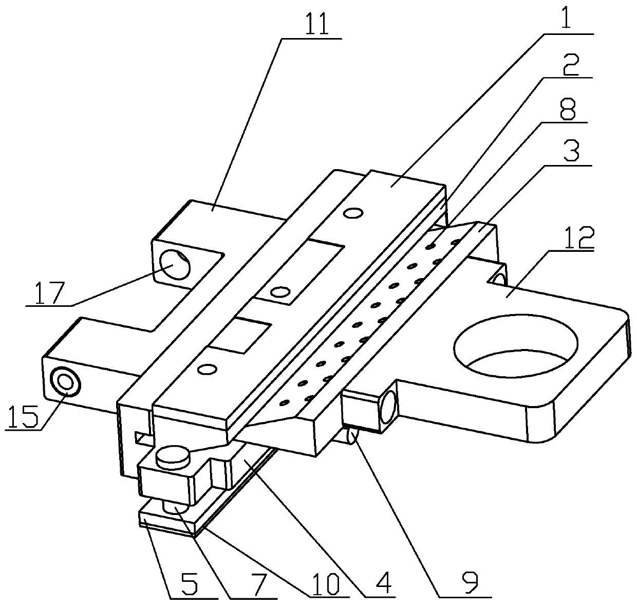
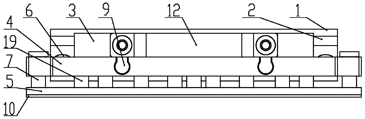
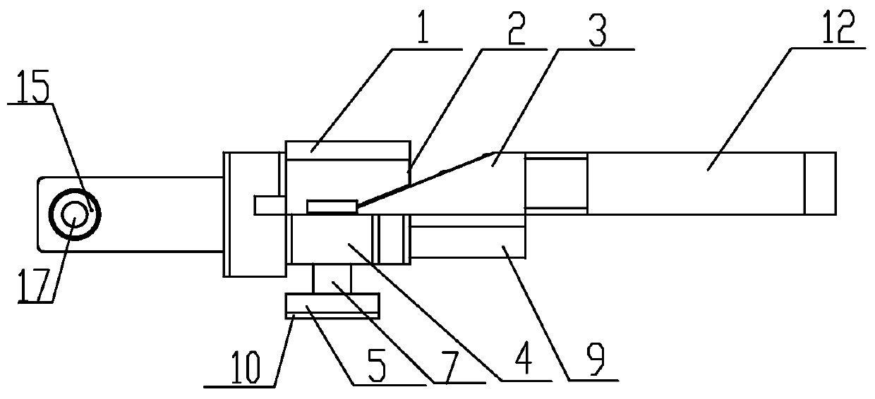
[0030] A lithium-ion battery lug anti-bending adjustment assembly, including a PCB board 1, a PCB mounting board 2, a wedge block 3, a main board 4 and a pressing block 5, the PCB board 1 is fixedly installed on the upper surface of the PCB mounting board 2, The upper surface of the wedge block 3 is slidingly connected to the lower surface of the PCB mounting board 2, the lower surface of the wedge block 3 is slidingly connected to the upper surface of the main board 4, and the pressing block 5 is installed on the main board 4, the left and right movement of the wedge block 3 pushes the PCB mounting board 2 and the main board 4 to move in opposite directions.

[0031] Further, the upper surface of the main board 4 is connected to the lower surface of the PCB mounting board 2 through at least one vertically arranged spring I, the upper surface of the main board 4 is vertically provided with at least one guide column I6, and the PCB The mounting plate 2 is provided with at least...

specific Embodiment approach 2

[0041] A clamp for applying the adjustment assembly described in Embodiment 1, comprising several adjustment assemblies, several clamp laminates 13 arranged vertically and parallel to each other, each of the two ends of the clamp laminate 13 is installed with a Adjustment components set vertically.

[0042] Further, the main board 4 of the adjustment assembly is vertically installed on the fixture layer 13 .

[0043] Further, the clamp also includes a guide post III14, which is fixed on the clamp laminate 13 along the width direction of the clamp laminate 13, and the connecting piece 11 integrally connected with the main board 4 in the adjustment assembly is passed through a linear bearing 15 is slidably connected to the guide post III 14, the installation direction of the adjustment components at the same end of two adjacent clamp laminates 13 is the same, and the installation direction of the adjustment components at both ends of each clamp laminate 13 is opposite.

[0044]...


PUM


Abstract

The invention discloses a lithium ion battery lead anti-bending adjustment assembly and a fixture, which belong to the technical field of lithium ion battery devices. In the specific scheme, the lithium ion battery lead anti-bending adjustment assembly comprises a PCB, a PCB mounting board, a wedge block, a main board and a pressing block, wherein the PCB is fixedly mounted on the upper surface ofthe PCB mounting board; the upper surface of the wedge block is in sliding connection with the lower surface of the PCB mounting board; the lower surface of the wedge block is in sliding connection with the upper surface of the main board; the pressing block is mounted on the lower surface of the main board; and the wedge block moves left and right to push the PCB mounting board and the main board to move to opposite directions. The PCB vertical direction and the battery thickness direction can be adjusted, the lead of the battery during formation and capacity grading processes is ensured notto be bent, the problems of battery short circuit, poor battery voltage, poor capacity and the like caused by bending of the lead are improved, and the lithium ion battery formation and sorting yieldis improved.

Description

technical field [0001] The invention belongs to the technical field of lithium-ion battery equipment, and in particular relates to a lithium-ion battery lug anti-bending adjustment assembly and a clamp using the adjustment assembly. Background technique [0002] Most of the existing soft-pack lithium-ion battery automatic hot-press formation and capacity separation equipment use formation cardboard to cover the battery formation. When replacing the next type of battery for production, the position of the battery tabs is different in the vertical direction and the battery thickness direction. Variety. However, the PCB board in contact with the lug on the layer board of the existing formation and capacity separation fixture can only change the position in the vertical direction, and the position in the thickness direction of the battery remains unchanged, resulting in the formation and capacity separation fixture pressing the battery. The phenomenon of battery tab bending, wh...

Claims


Application Information

Patent Timeline
Patent Type & Authority Applications(China)
IPC IPC(8): H01M10/058H01M2/26
CPCH01M10/058H01M50/531Y02E60/10Y02P70/50
Inventor 朱永康穆俊杰曾玉祥徐延铭
Owner ZHUHAI COSMX BATTERY CO LTD
Why Eureka
Try Eureka