Fastening device, system and method for connector

A connector and mating state technology, applied in the direction of connecting/disconnecting the connecting device, can solve the problems of inconsistent position, assembly error, unstable deviation of BTB connector, etc., and achieve the effect of avoiding assembly error

Active Publication Date: 2019-10-15
OPPO CHONGQING INTELLIGENT TECH CO LTD
View PDF5 Cites 2 Cited by
  • Summary
  • Abstract
  • Description
  • Claims
  • Application Information

AI Technical Summary

Problems solved by technology

[0003] In related technologies, during the fastening process of the BTB connector, the fastening process is guided by visual positioning technology. Specifically, after the position is calibrated, the BTB connector that is fastened later needs to make room for the BTB connector that is fastened first. The drop difference prevents the BTB connectors that are snapped back from interfering with the fastening process of the BTB connectors that are snapped first. In this way, the BTB connectors that are snapped back need to be raised and lowered during the period from visual positioning to before snapping Once, the BTB connector caused an unstable offset relative to the manipulator and other driving mechanisms, which was inconsistent with the position during visual positioning, resulting in a large assembly error

Method used


Image

  • Fastening device, system and method for connector
  • Fastening device, system and method for connector
  • Fastening device, system and method for connector

Examples


Embodiment Construction

[0032] It should be noted that, in the case of no conflict, the embodiments in the application and the technical features in the embodiments can be combined with each other. Undue Limitation of This Application.

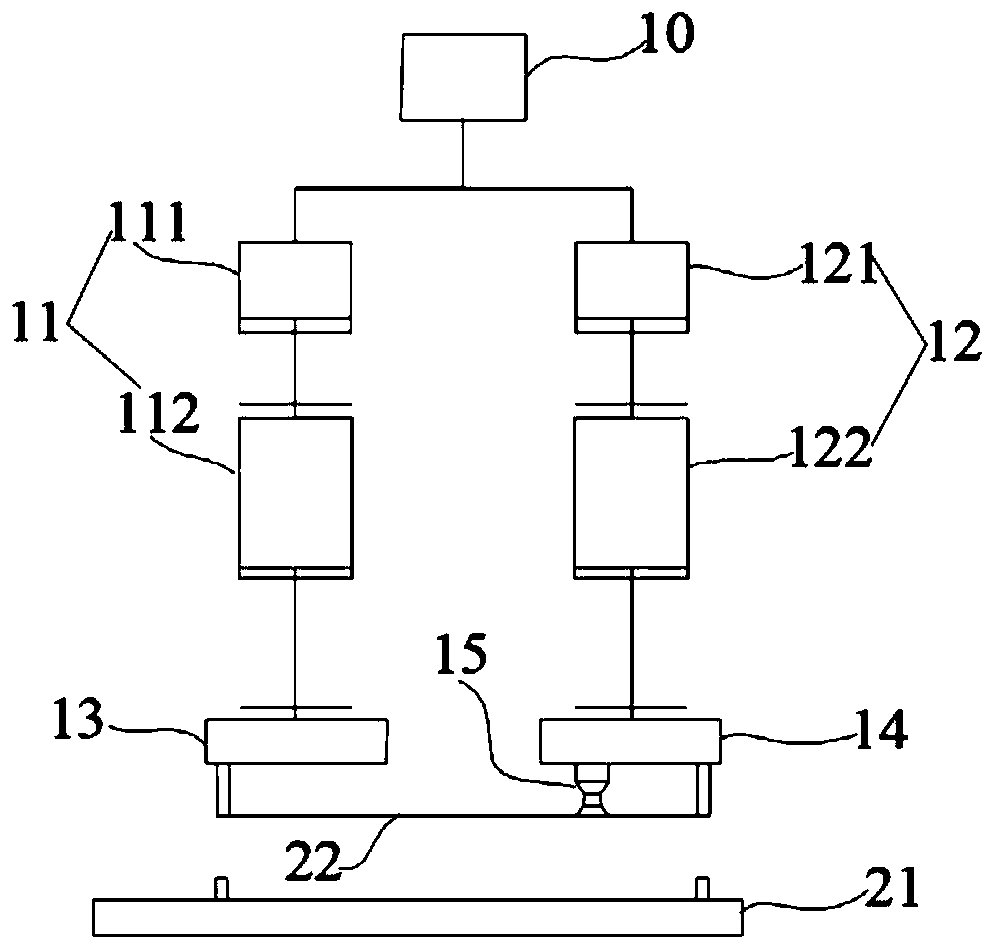
[0033] In the description of this application, "up", "down", "left", "right" orientations or positional relationships are based on the attached figure 1 It should be understood that these orientation terms are only for the convenience of describing the application and simplifying the description, rather than indicating or implying that the referred device or element must have a specific orientation, be configured in a specific orientation, and operation and therefore should not be construed as limiting the application.

[0034] An embodiment of the present application provides a fastening device for a connector, that is, the fastening device is used to fasten the connector. The connector includes mating male and female structures, and the male and female structures...


PUM


Abstract

The embodiment of the present application provides a fastening device, system and method for a connector. The fastening device comprises a driving mechanism, a first material-acquiring portion, a second material-acquiring portion, a first telescopic mechanism, and a second telescopic mechanism , wherein the first telescopic mechanism includes a first telescopic cylinder and a second telescopic cylinder; the first material-acquiring portion is disposed at one end of the first telescopic mechanism; the second telescopic mechanism includes a third telescopic cylinder; the second material-acquiring portion is disposed at one end of the second telescopic mechanism; and the driving mechanism drives the first telescopic mechanism and the second telescopic mechanism to move synchronously. The fastening device in the embodiment of the present application can form a positive first fastening drop before calibrating a position by the cooperation of the first telescopic mechanism and the second telescopic mechanism, and can form a negative second fastening drop after calibrating the position and fastening one group of connectors. After the calibration of the position, two first fastening jointshave no relative motion with respect to the driving mechanism, so that the connector can be buckled accurately according to the theoretically calculated displacement to avoid uncontrollable assemblyerrors.

Description

technical field [0001] The present application relates to the technical field of conductive connection of electrical components, and in particular to a buckling device, a buckling system, and a buckling method of a connector. Background technique [0002] The BTB connector (board to borad, board-to-board connector) is used to connect two PCBs (Printed CircuitBoard, printed circuit boards), so that the two PCBs can be mechanically and electrically connected. It is characterized by male and female connectors Use in pairs. [0003] In related technologies, during the fastening process of the BTB connector, the fastening process is guided by visual positioning technology. Specifically, after the position is calibrated, the BTB connector that is fastened later needs to make room for the BTB connector that is fastened first. The drop difference prevents the BTB connectors that are snapped back from interfering with the fastening process of the BTB connectors that are snapped firs...

Claims


Application Information

Patent Timeline
IPC IPC(8): H01R43/26
CPCH01R43/26
Inventor 魏巍
Owner OPPO CHONGQING INTELLIGENT TECH CO LTD
Why Eureka
Try Eureka