Transformer substation inspection robot

A technology for inspection robots and substations, applied in the field of robots, can solve the problems of low flexibility of use, single function of the protective cover, and cumbersome disassembly and assembly of the protective cover, so as to improve the convenience of disassembly and assembly, increase the flexibility of use, and extend the The effect of overall length

Inactive Publication Date: 2019-10-18
杭州朝丽科技有限公司
View PDF0 Cites 4 Cited by
  • Summary
  • Abstract
  • Description
  • Claims
  • Application Information

AI Technical Summary

Problems solved by technology

[0003] When the existing substation inspection robot is in use, a camera is symmetrically arranged on the top of the device to monitor the power transmission and transformation equipment. Since the device is used outdoors, it is protected by a protective cover set on the top surface of the camera, and the protective cover is connected to the camera. It is fixed by multiple bolts, and alignment is required during the connection process, which makes disassembly and assembly of the protective cover cumbersome in the case of regular replacement, and the protective cover itself has a single function and is not flexible in use. problem, for this reason the present invention proposes substation inspection robot

Method used


Image

  • Transformer substation inspection robot
  • Transformer substation inspection robot
  • Transformer substation inspection robot

Examples


Embodiment 1

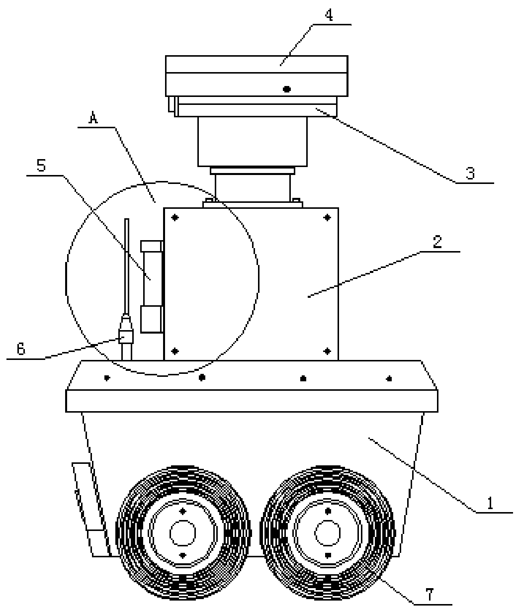
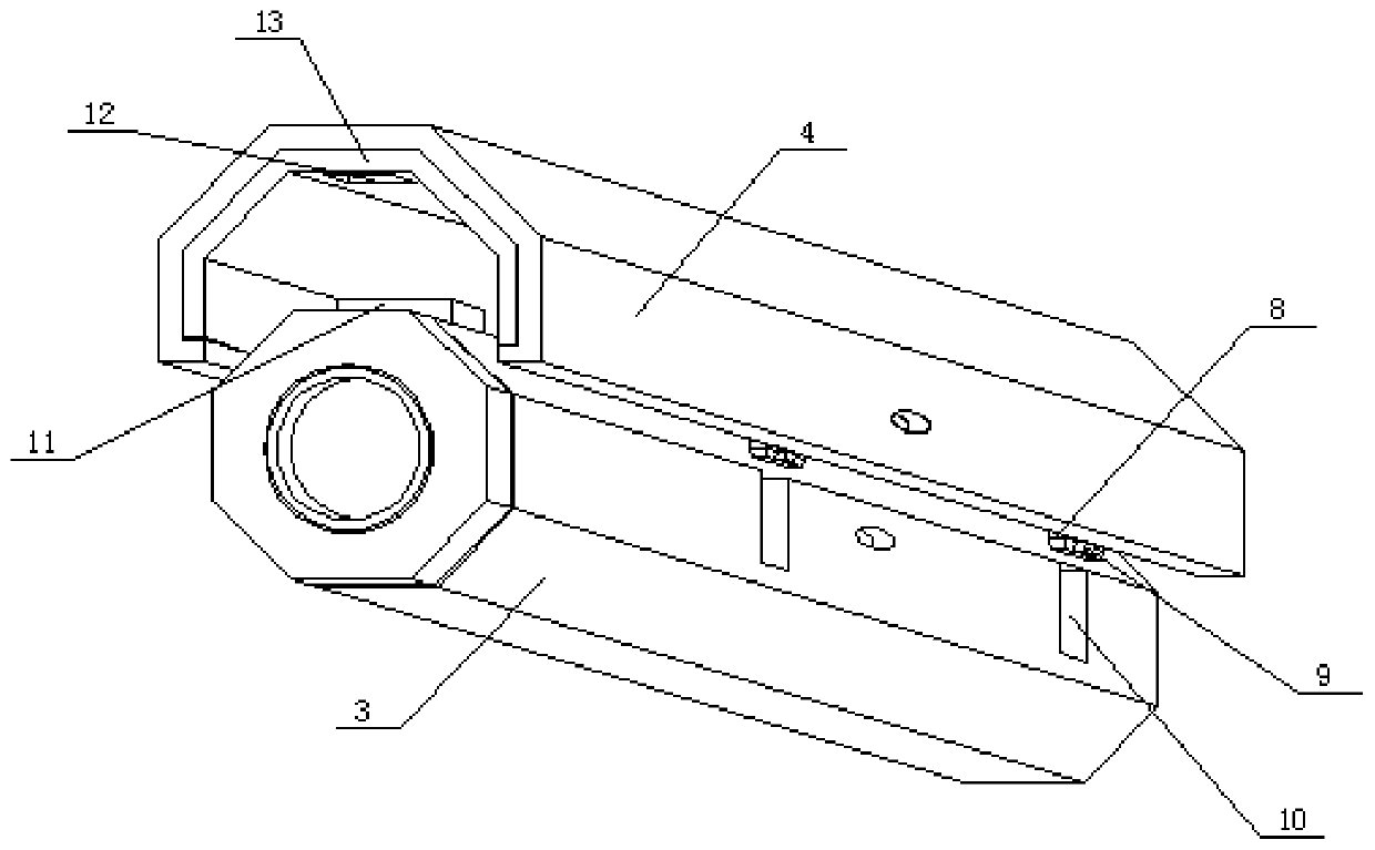
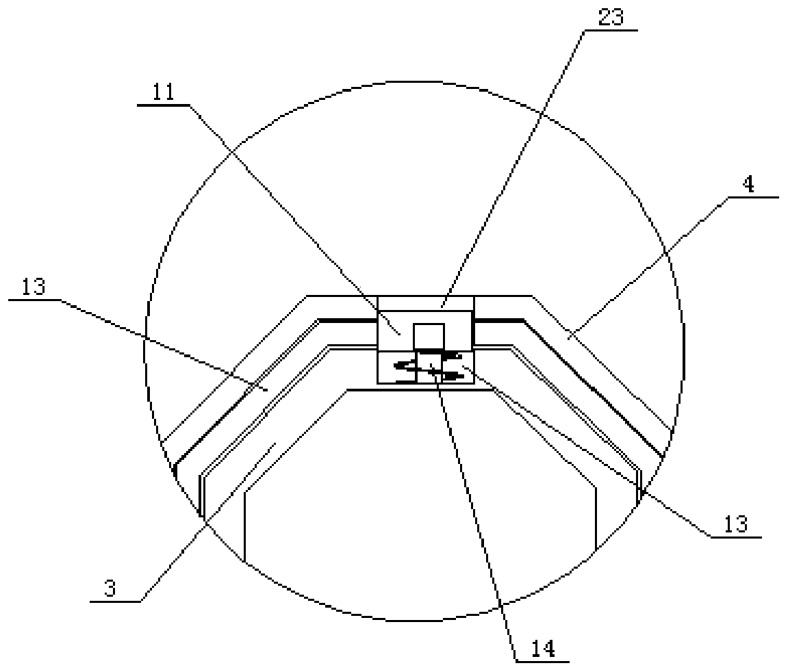
[0023] see Figure 1 to Figure 3 , the present invention provides a technical solution: substation inspection robot, including a main body 1, an operating device 2 is arranged on the top of the main body 1, and a camera 3 is symmetrically fixed on both sides of the top of the operating device 2, and a protective cover is arranged on the top of the camera 3 4. A connecting plate 13 is embedded inside the protective cover 4, and the surface of the connecting plate 13 is provided with a groove 12. The inner wall of the protective cover 4 is symmetrically fixed with a limit block 8 on both sides, and the end of the limit block 8 is fixed with a Connecting block 9, the two sides of the surface of camera 3 are symmetrically provided with the limit groove 10 that matches with limit block 8, and the top of camera 3 is provided with connecting plate 13, and the inside of connecting plate 13 is provided with block 11, protective cover 4 and the inside of the connection plate 13 are prov...

Embodiment 2

[0025] see Figure 1 to Figure 5 , the present invention provides a technical solution: substation inspection robot, including a main body 1, an operating device 2 is arranged on the top of the main body 1, and a camera 3 is symmetrically fixed on both sides of the top of the operating device 2, and a protective cover is arranged on the top of the camera 3 4. A connecting plate 13 is embedded inside the protective cover 4, and the surface of the connecting plate 13 is provided with a groove 12. The inner wall of the protective cover 4 is symmetrically fixed with a limit block 8 on both sides, and the end of the limit block 8 is fixed with a Connecting block 9, the two sides of the surface of camera 3 are symmetrically provided with the limit groove 10 that matches with limit block 8, and the top of camera 3 is provided with connecting plate 13, and the inside of connecting plate 13 is provided with block 11, protective cover 4 and the inside of the connection plate 13 are prov...


PUM


Abstract

The invention discloses a transformer substation inspection robot. The transformer substation inspection robot comprises a main body, wherein an operating device is arranged at the top of the main body, a camera is symmetrically fixed on the two sides of the top of the operating device, a protective cover is arranged at the top of the camera, and a connecting plate is embedded inside the protective cover; the protective cover and the camera are clamped and connected initially through a sliding limiting mode through the designed a limiting block, a connecting block and a limiting groove, so that the camera is automatically aligned with a through hole formed in the surface of the protective cover and then is fixed through an external bolt through the through hole, so that the protective cover can be conveniently mounted; through the designed a groove, the connecting plate, a clamping block and a spring, the overall length of the protective cover can be extended according to actual use requirements of workers, so that when the transformer substation inspection robot is used in severe weather, through the extension of the connecting plate, the camera is further protected, so that the use flexibility of the protective cover is improved.

Description

technical field [0001] The invention belongs to the technical field of robots, and in particular relates to a substation inspection robot. Background technique [0002] The substation inspection robot is a device for round-the-clock inspection, data collection, video monitoring, temperature and humidity measurement, and air pressure detection of power transmission and transformation equipment to improve the safe operation of equipment in the transmission and transformation substation. [0003] When the existing substation inspection robot is in use, a camera is symmetrically arranged on the top of the device to monitor the power transmission and transformation equipment. Since the device is used outdoors, it is protected by a protective cover set on the top surface of the camera, and the protective cover is connected to the camera. It is fixed by multiple bolts, and alignment is required during the connection process, which makes disassembly and assembly of the protective co...

Claims


Application Information

Patent Timeline
Patent Type & Authority Applications(China)
IPC IPC(8): B25J19/00B25J19/04B25J11/00
CPCB25J19/00B25J19/04B25J11/00
Inventor 王洪根
Owner 杭州朝丽科技有限公司
Why Eureka
Try Eureka