Parking system capable of automatically parking based on electromechanical control

An automatic parking and parking system technology, applied in the field of parking systems, can solve the problems of lack of intelligent guidance and parking in parking lots, and the inability of parking lots to achieve automatic parking, and achieve the effect of reducing the time to find a parking space.

Active Publication Date: 2019-10-18
YELLOW RIVER CONSERVANCY TECHN INST
View PDF7 Cites 3 Cited by
  • Summary
  • Abstract
  • Description
  • Claims
  • Application Information

AI Technical Summary

Problems solved by technology

[0007] Aiming at the deficiencies of the prior art, the present invention provides a parking system based on electromechanical control for automatic parking, which solv

Method used


Image

  • Parking system capable of automatically parking based on electromechanical control
  • Parking system capable of automatically parking based on electromechanical control
  • Parking system capable of automatically parking based on electromechanical control

Examples


Embodiment 1

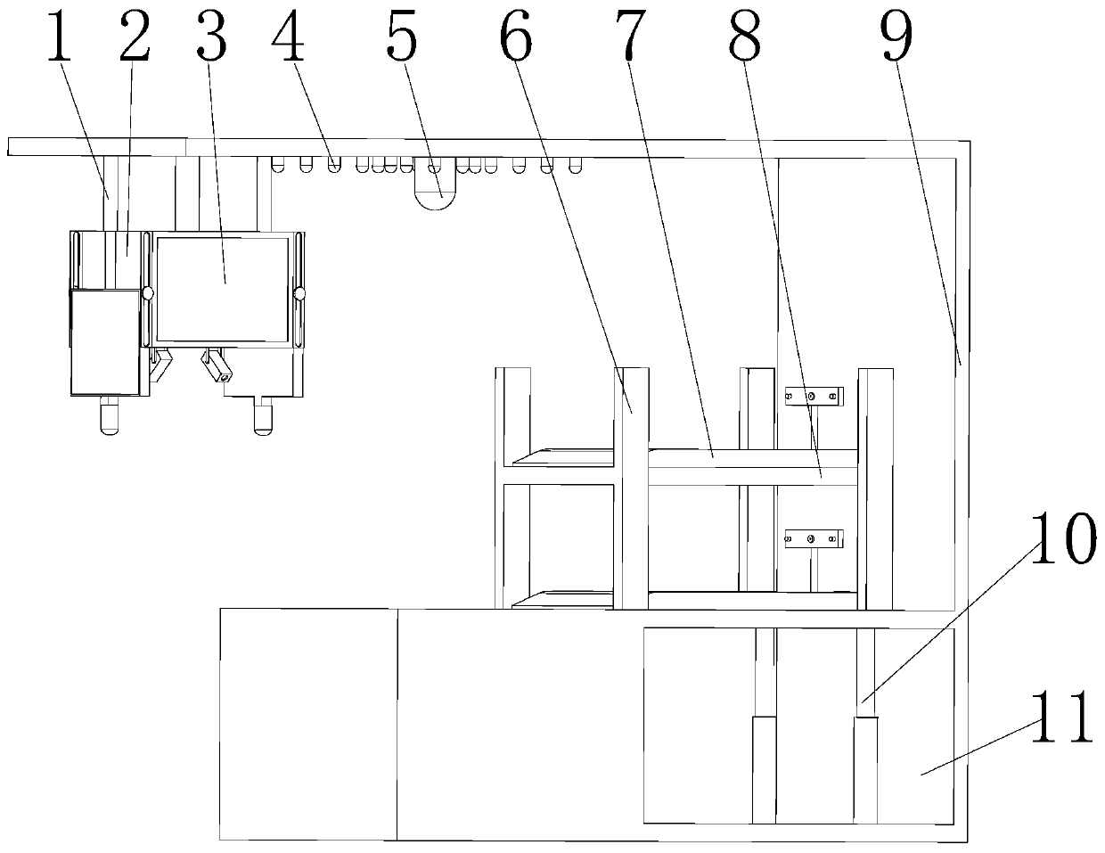
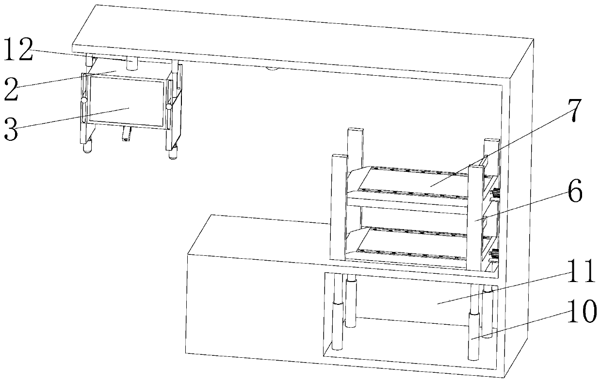
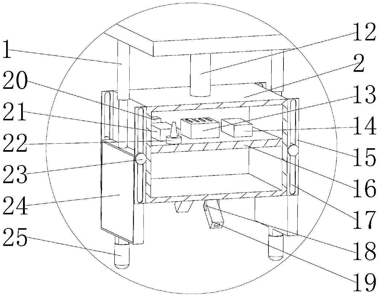
[0029] see Figure 1-6As shown, the parking system based on electromechanical control automatic parking in a preferred embodiment of the present invention includes a mobile station 7, a fixed station 8 and a wall 9, and at least two mobile stations 7 are aligned up and down. Both sides of the bottom are aligned with draw-in grooves 31, and at the same time, on the top surface of the fixed platform 8 directly below the draw-in grooves 31, a clamp bar 33 is arranged. A storage chamber 11 is arranged on the body of wall 9, and four hydraulic cylinders 10 are fixedly connected on the wall body 9 at the bottom of the storage chamber 11, and a camera 5 is fixedly installed on the top and bottom surface of the wall body 9 on one side of the mobile platform 7. , while the other side of the camera 5 is provided with an installation box 2, the inside of the installation box 2 is provided with an installation plate 16, and the top center of the installation plate 16 is provided with a PL...

Embodiment 2

[0032] A servomotor 34 is arranged at the center position outside one end of the fixed platform 8, and the output end of the servomotor 34 is fitted with a screw rod 32, and the other end of the screw rod 32 passes through the screw connection between the fixed platform 8 and the mobile platform 7 simultaneously, and the servomotor 34 is electrically connected to the PLC controller 13 through conductive wires, and the servo motor 34 and the camera 5 are respectively located on both sides of the mobile platform 7 . Infrared emitters 4 are uniformly arranged on the bottom surface of the top of the walls 9 on both sides of the camera 5 , and the infrared emitters 4 are electrically connected to the PLC controller 13 through conducting wires.

Embodiment 3

[0034] The two opposite sides of the installation box 2 are provided with guide screens 3, while the outer sides of the other two opposite sides of the installation box 2 are provided with guide screens 24. are respectively electrically connected to the digital-to-analog conversion modules 20 . The top center position of guide screen 24 is fixedly connected on the top bottom surface of body of wall 9 by electric telescopic rod 1, and the bottom center position of described guide screen 24 is fixedly installed with warning light 25 simultaneously, and described electric telescopic rod 1 and warning light 25 The electric telescopic rod 1 is vertically aligned with the camera 5 and is respectively electrically connected to the PLC controller 13 through conducting wires. Preferably, both the guide screen 3 and the guide screen 24 are LED display screens, the guide screen 3 is used to display the license plate number of the parking position, and the guide screen 24 is used to displ...


PUM


Abstract

The invention discloses a parking system capable of automatically parking based on electromechanical control. The system comprises moving tables, fixed tables and a wall. At least two moving tables are arranged in an up and down aligning manner, the fixed tables are arranged below the moving tables in an aligned manner, the fixed tables are fixedly connected through a connecting plate, hydraulic cylinders are fixedly connected to the four corners of the bottom face of the fixed table on the bottommost part, clamping grooves are formed in the two sides of the bottom of each moving table in an aligned manner, meanwhile, clamping strips are arranged at the positions, under the clamping grooves, of the top faces of the fixed tables, and are clamped in the clamping grooves in a sliding manner,storage cavities are formed in the positions, below the fixed tables, of the wall, cameras are fixedly mounted at the positions, on one sides of the moving tables, of the bottom face of the top of thewall, mounting boxes are arranged on the other sides of the cameras, and PLCs are arranged in the mounting boxes. Through a guide screen, the PLCs, a wireless signal transceiver, a license plate detector, a guide screen, the cameras and the moving tables, the problem that an existing parking site lacks the intelligent guide parking function and cannot achieve the automatic parking is solved.

Description

technical field [0001] The invention relates to the technical field of automatic parking, in particular to a parking system for automatic parking based on electromechanical control. Background technique [0002] The parking lot can be simply defined as a place where cars are parked. With the advancement of science and technology, the rapid development of my country's economy and the acceleration of urbanization, the number of urban family car ownership continues to increase, and people's demand for parking lots for cars is increasing day by day. The requirements are also getting higher and higher, whether it is a living place, a workplace or a large shopping mall, there are a large number of parking lots to facilitate the parking of cars. [0003] But existing technology has following deficiency: [0004] 1. The existing parking lot lacks the function of intelligently guiding parking. Although the existing parking lot will be equipped with a device at the entrance of the par...

Claims


Application Information

Patent Timeline
IPC IPC(8): E04H6/42
CPCE04H6/422
Inventor 王瑨王艳凤王艺颖牛聪翟保尊张宏祥史龙飞王海博曹丽芳
Owner YELLOW RIVER CONSERVANCY TECHN INST
Why Eureka
Try Eureka