Method and system for estimating engine speed

An engine speed and engine technology, applied in the direction of engine control, machine/engine, calculation, etc., can solve the problems of inability to obtain data, difficult to obtain engine speed, and inability to add a speed sensor, and achieve easy implementation, improve speed calculation efficiency, and calculate simple effect

Active Publication Date: 2020-05-22
SHANDONG UNIV
View PDF6 Cites 0 Cited by
  • Summary
  • Abstract
  • Description
  • Claims
  • Application Information

AI Technical Summary

Problems solved by technology

The inventor found in the research and development process that the engine speed is difficult to obtain, and there are also the following problems: (1) not every vehicle has an OBD system, especially old vehicles; (2) the CAN bus communication protocol of the whole vehicle is not open, and cannot Obtain data directly from the CAN bus; (3) The engine body cannot be damaged so that an external speed sensor cannot be added
Experiments without access to engine speed are meaningless

Method used


Image

  • Method and system for estimating engine speed
  • Method and system for estimating engine speed
  • Method and system for estimating engine speed

Examples


Embodiment 1

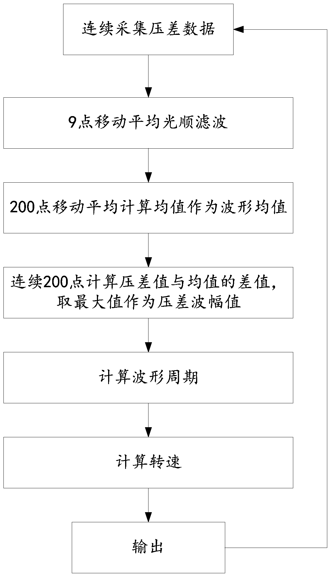
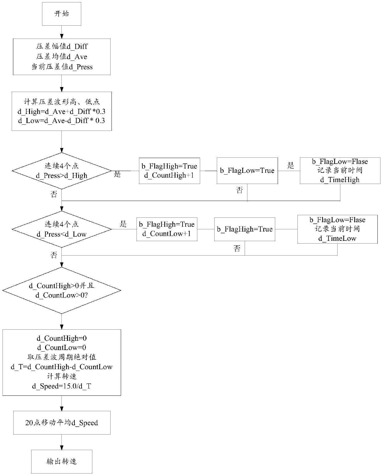
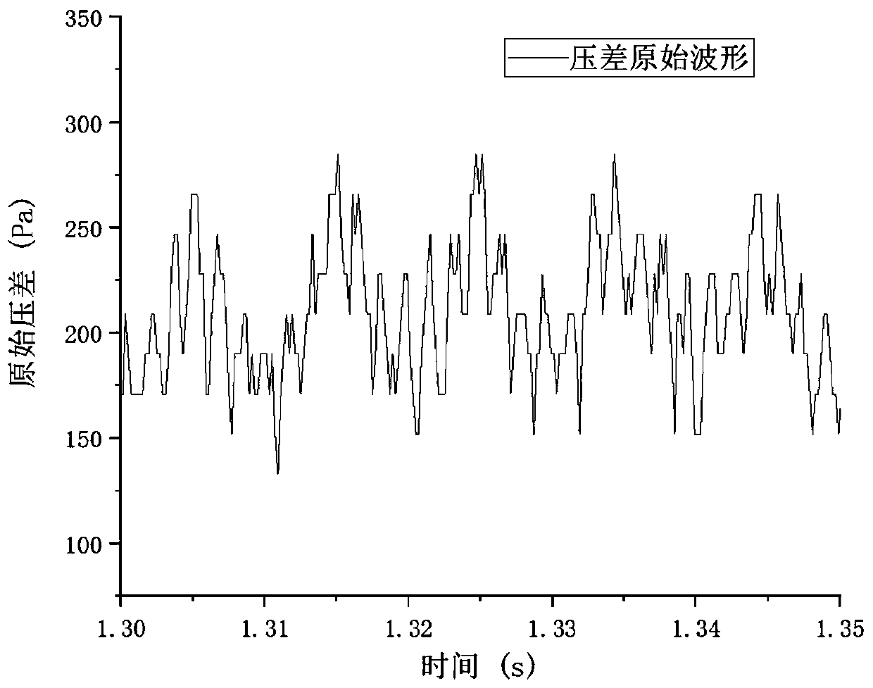
[0052] This embodiment provides a method for estimating the engine speed based on the exhaust pressure wave, which calculates the engine speed through the fundamental frequency of the differential pressure wave of the engine exhaust.

[0053] Assuming that a 4-stroke m-cylinder engine works at a speed of n r / min, the number of cycles d_Cycle of the engine per second is:

[0054]

[0055] In each cycle, all cylinders perform work in turn, that is, all cylinders do work in total every second. Secondary work, and each cylinder does work once, which is a differential pressure wave. Therefore, the number of differential pressure waves that the engine should have at the current speed, that is, the fundamental frequency d_f of the exhaust pressure differential wave of the engine is:

[0056]

[0057] Therefore, if the fundamental frequency d_f of the differential pressure wave of the engine exhaust can be calculated, the engine rotational speed n can be inversely deduced accor...

Embodiment 2

[0096] This embodiment provides an engine speed estimation system based on exhaust pressure waves, the system includes:

[0097] The data acquisition module is used to continuously acquire the engine exhaust pressure difference data at the current moment, and perform multi-point moving average smoothing filter processing on it to obtain the engine exhaust pressure difference value at the current moment;

[0098] The differential pressure waveform average value calculation module is used to calculate the average value of the engine exhaust pressure differential waveform by using a multi-point moving average method;

[0099] The pressure difference waveform amplitude calculation module is used to calculate the difference between the current engine exhaust pressure difference value and the engine exhaust pressure difference waveform average value, and the engine exhaust pressure difference value corresponding to the maximum value of the difference is taken as the engine exhaust pr...


PUM


Abstract

The invention discloses a method and system for estimating engine speed. The method comprises the following steps: continuously acquiring the data of the engine exhaust pressure difference at the current moment, and performing multi-point moving average smoothing filter processing on it to obtain the engine exhaust pressure at the current moment Difference; use the multi-point moving average method to calculate the average value of the engine exhaust pressure difference waveform; calculate the difference between the current engine exhaust pressure difference value and the engine exhaust pressure difference waveform average value, and take the maximum value of the difference as the engine exhaust pressure difference waveform Amplitude; use the amplitude of the engine exhaust differential pressure waveform, the average value of the engine exhaust differential pressure waveform, and the engine exhaust differential pressure value to calculate the engine exhaust differential pressure waveform period; use the engine exhaust differential pressure waveform period to calculate the engine speed.

Description

technical field [0001] The invention relates to the technical field of engine testing, in particular to an engine speed estimation method and system based on exhaust pressure waves. Background technique [0002] As an indispensable power output device for human society, the engine plays a vital role in our daily life. From the design and development of the engine to the loading application, there are several tests in the middle, including emission tests, power and economy tests, etc. In the current tests that use the engine as the test object, the engine speed is a parameter that must be known for these tests, and it is an intuitive parameter for the external work of the engine. [0003] During the test, the engine speed is not easy to obtain. At present, the main way to obtain the speed is to install a magnetoelectric or Hall sensor on the flywheel housing. [0004] However, there are certain problems in this method. It is installed at the flywheel cover, close to the rin...

Claims


Application Information

Patent Timeline
Patent Type & Authority Patents(China)
IPC IPC(8): F02D45/00G06K9/00
CPCF02D31/001G06F2218/10
Inventor 程勇于文龙刘静远
Owner SHANDONG UNIV
Why Eureka
Try Eureka