Flow regulating and pressure regulating valve

A pressure regulating valve and flow regulating technology, which is applied in the field of flow regulating and pressure regulating valves, can solve problems such as inability to disassemble and affect the adjustment accuracy of the valve, and achieve the effects of reducing pipeline pressure, reducing the impact of water flow, and facilitating maintenance

Pending Publication Date: 2019-10-18
TIANJIN CARLS VALVE CO LTD
View PDF0 Cites 0 Cited by
  • Summary
  • Abstract
  • Description
  • Claims
  • Application Information

AI Technical Summary

Problems solved by technology

But at the same time, because the sleeve is fixed in the guide body of the valve body and cannot be disassembled, the valve is actually often used at a small opening, which affects the adjustment accuracy of the valve.

Method used


Image

  • Flow regulating and pressure regulating valve
  • Flow regulating and pressure regulating valve
  • Flow regulating and pressure regulating valve

Examples


Embodiment 1

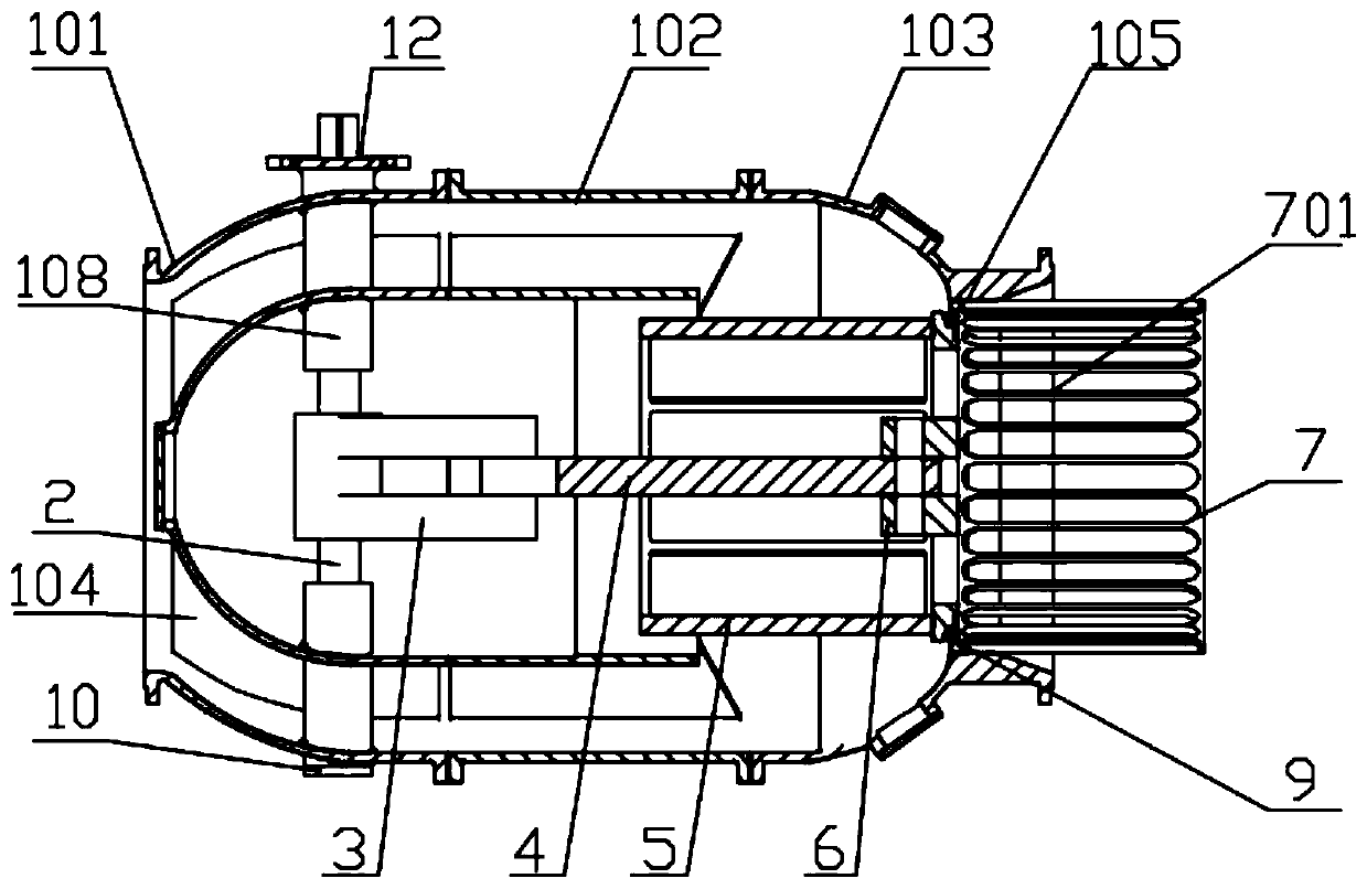
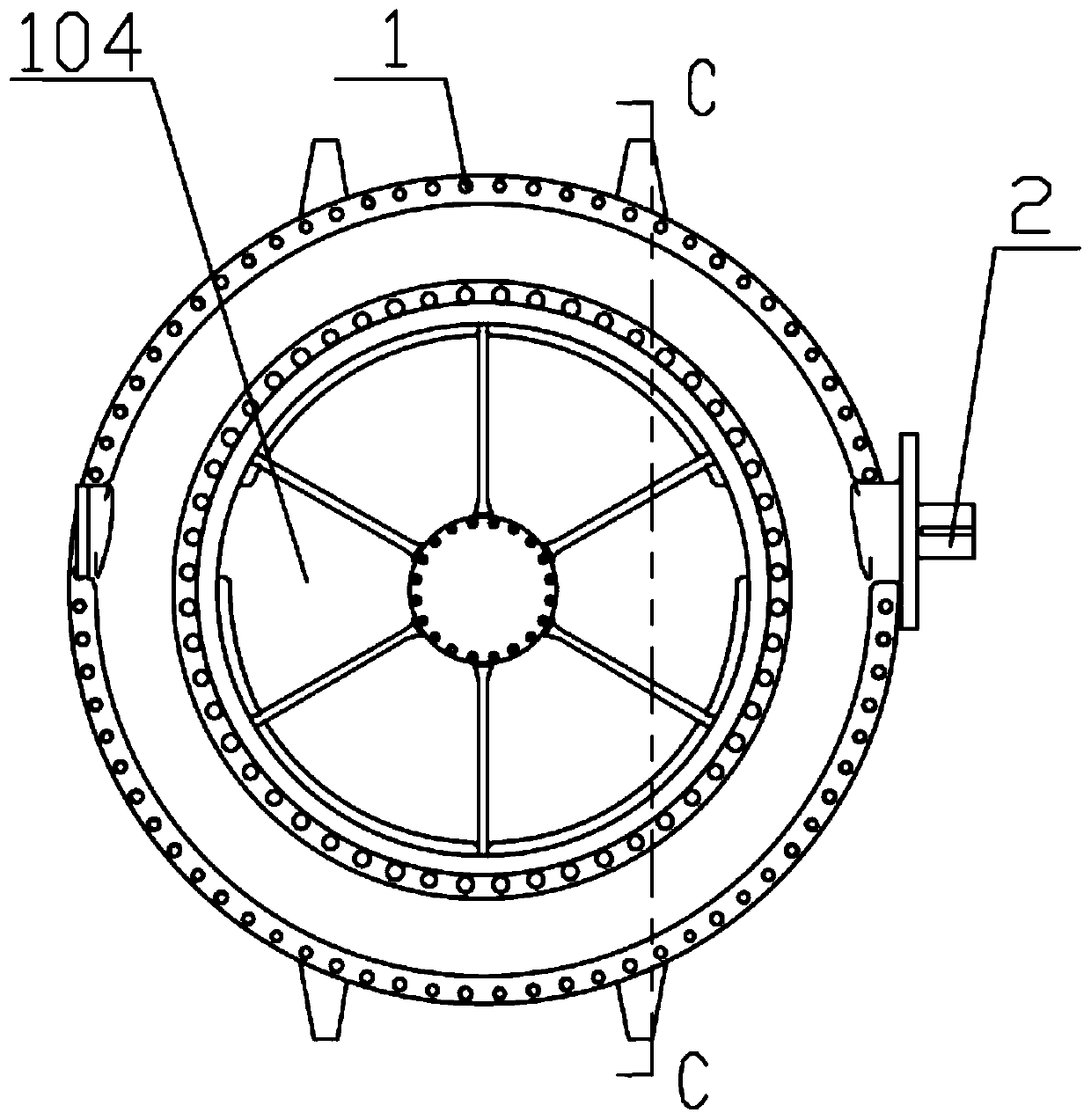
[0041] Embodiment 1: The valve body 1 is sequentially connected and fixed by the left valve body 101 and the right valve body 102 through double stud screws. There is a guide tube 107 inside the valve body 1. The guide tube 107 and the left valve body 101 are integrally connected. The end of the flow tube 107 near the water outlet is an open structure, the water flow channel 106 is between the flow guide tube 107 and the valve body, the left end of the left valve body 101 is the water inlet 104, the right end of the right valve body 102 is the water outlet 105, and the piston 6 is arranged at the outlet. The water outlet 105 is in contact with the water outlet 105. The piston 6 is connected to the rocker arm 3 through the connecting rod. The rocker arm 3 is sleeved on the rotating shaft 2. The rotating shaft 2 controls the piston 6 to move linearly through the driving device. The rotating shaft 2 is located in the water flow channel. 106 places are sheathed in the support sleev...

Embodiment 2

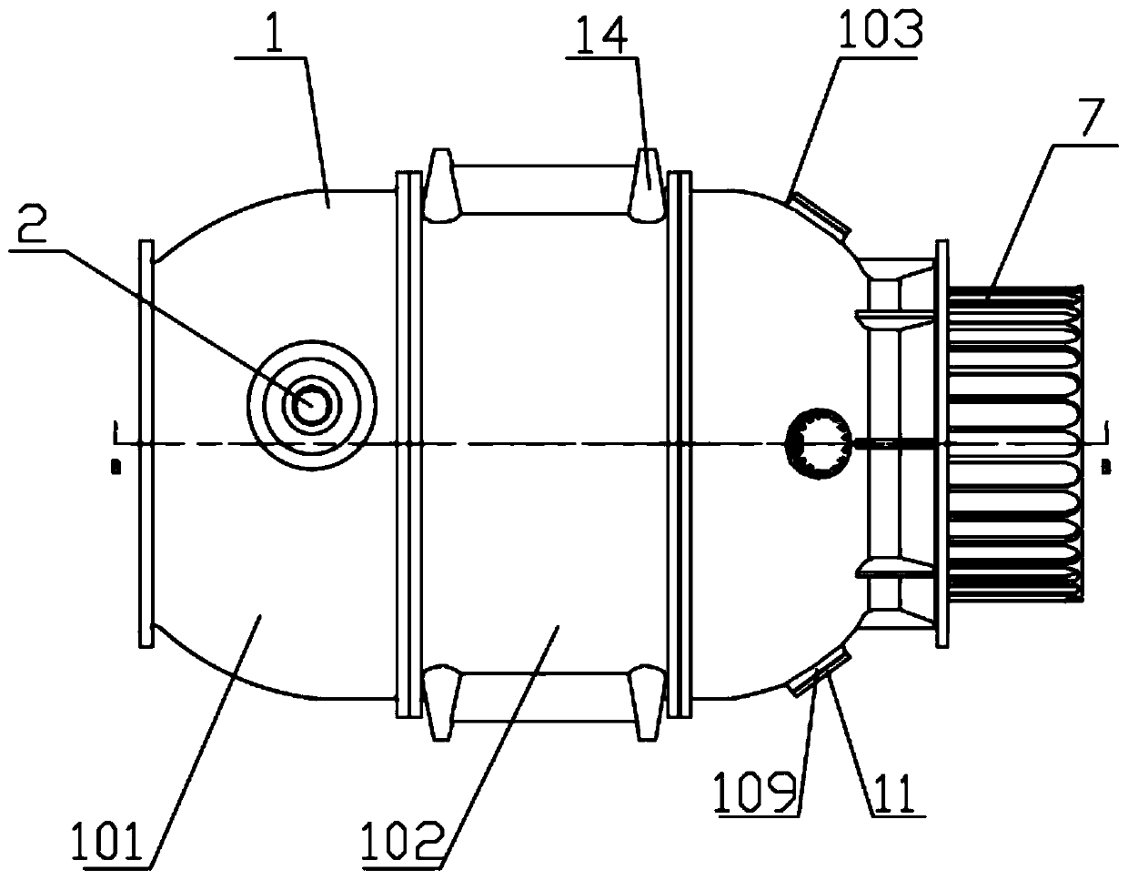
[0042] Embodiment 2: The difference from Embodiment 1 is that the valve body 1 is sequentially connected and fixed by the left valve body 101, the middle valve body 102 and the right valve body 103 through double stud screws. 7 is connected and fixed with the piston 6, and the rotating shaft 2 drives the restrictor cover 7 and the spool 5 to perform linear motion through the rocker arm 3, and the restrictor cover 7 is slidingly connected with the inner wall of the water outlet 105, and plays a role in the movement of the piston 6 and the spool 5. Guiding function, there are flow holes 701 on the flow limiting cover 7, and the flow holes 701 are oblong holes arranged in sequence. The driving device controls the size of the gap between the piston 6 and the water outlet 105 to control the flow of water. Reduce the impact force of water flow and reduce pipeline pressure.


PUM


Abstract

The invention provides a flow regulating and pressure regulating valve, and belongs to the field of valves. The flow regulating and pressure regulating valve comprises a valve body, wherein the valvebody is at least divided into two parts, namely a left valve body and a right valve body; a water inlet is formed in the left side of the left valve body, the left valve body is internally provided with a flow guide cylinder which is integrally connected with the left valve body, and a water flow channel is formed between the flow guide cylinder and the valve body; the right end of the right valvebody is provided with a water outlet, the side wall of the right valve body is provided with a sewage outlet, the sewage outlet is close to the water outlet, a piston is arranged at the water outlet,the piston and the contact surface of the water outlet is tightly attached, and the piston is rotationally connected with a rocker arm through a connecting rod; the rocker arm is connected to a rotating shaft in a sleeving mode, the rotating shaft penetrates through the side wall of the left valve body, the end, extending out the side wall, of the rotating shaft is connected with a driving device, and the rotating shaft drives the piston to linearly move through the driving device. The flow regulating and pressure regulating valve has the advantages that the water flow size is automatically adjusted, the pipeline impact force is reduced, the pipeline pressure is reduced, and the flow regulating and pressure regulating valve is flexible and reliable.

Description

technical field [0001] The invention belongs to the field of valves and relates to a flow regulating and pressure regulating valve. Background technique [0002] At present, the commonly used piston-type flow regulating and pressure regulating valve changes the area of ​​the orifice on the sleeve through the movement of the piston, so as to realize the function of regulating flow and pressure under high pressure difference and eliminating cavitation. Because of its unique function, its price is expensive. Generally, when installing this valve in a project, a valve with a size larger than the actual use will be selected to prepare for future project expansion. But at the same time, because the sleeve is fixed in the guide body of the valve body and cannot be disassembled, the valve is actually often used under a small opening, which affects the adjustment accuracy of the valve. Contents of the invention [0003] The problem to be solved by the present invention is to provi...

Claims


Application Information

Patent Timeline
Patent Type & Authority Applications(China)
IPC IPC(8): F16K1/16F16K1/32F16K1/36F16K1/52F16K27/02F16K31/04F16K47/08
CPCF16K1/16F16K1/32F16K1/36F16K1/52F16K27/02F16K31/047F16K47/08
Inventor 王志坚
Owner TIANJIN CARLS VALVE CO LTD
Why Eureka
Try Eureka