Check patentability & draft patents in minutes with Patsnap Eureka AI!

Comprehensive automatic control system for lubricating oil pump station oil supply pressure and oil supply temperature

An automatic control system and oil supply temperature technology, applied in lubricating parts, engine temperature, engine lubrication, etc., can solve problems such as inability to perform dynamic real-time adjustment, inapplicability, and low oil supply pressure

Inactive Publication Date: 2019-10-18
HARBIN DONGAN ENGINE GRP
View PDF7 Cites 5 Cited by
  • Summary
  • Abstract
  • Description
  • Claims
  • Application Information

AI Technical Summary

Problems solved by technology

Disadvantages: (1) The pressure control accuracy is not high; (2) Dynamic real-time adjustment cannot be performed; (3) The flow rate has a great influence on the pressure stability. When the flow rate increases, the overflow valve does not overflow, resulting in a decrease in pressure; (4) The temperature has a great influence on the pressure stability. As the temperature rises, the system flow increases, which will also cause the overflow valve to not overflow, causing the pressure to drop.
Larger lubricating oil pump stations often adopt frequency conversion control system. This method is to adjust the speed of lubricating oil pump through frequency converter, and then change the oil supply pressure of lubricating oil. The higher the speed, the higher the oil supply pressure, and the lower the speed, the lower the oil supply pressure The lower; the disadvantage is that the equipment is complicated and the cost is higher, and it is not suitable for small and medium-scale lubricating oil circulation systems
[0003] In order to avoid excessive oil supply temperature in lubricating oil pumping stations, water-cooled radiators are often used to reduce the temperature of lubricating oil through circulating water. Traditional water-cooled radiators generally do not have automatic temperature control functions and cannot achieve constant oil supply temperature.

Method used


Image

  • Comprehensive automatic control system for lubricating oil pump station oil supply pressure and oil supply temperature
  • Comprehensive automatic control system for lubricating oil pump station oil supply pressure and oil supply temperature

Examples


Embodiment Construction

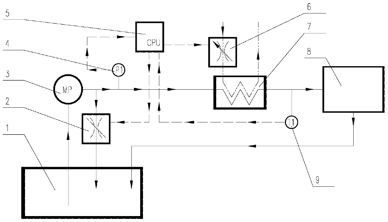
[0022] figure 1 It is a principle diagram of the present invention, wherein, the automatic pressure control system of the lubricating oil pumping station is composed of a lubricating oil tank 1, a lubricating oil pump 3, a lubricating mechanism 8, a regulating valve 2, connecting pipelines, a pressure transmitter 4, a digital controller 5, an electrical signal lines etc. In the figure, the thin solid lines with arrows indicate the connecting pipes and the flow direction of lubricating oil, and the dotted lines with arrows indicate the electrical signal lines and signal transmission directions. The lubricating oil flow path is: after the lubricating oil pump is started, the lubricating oil enters the lubricating oil pump 3 from the lubricating oil tank 1, and a part of the lubricating oil directly flows back to the lubricating oil tank from the lubricating oil pump outlet through the regulating valve 2 1. Part of the lubricating oil flows back to the lubricating oil tank 1 thr...


PUM


Abstract

The invention belongs to the technical field of automatic control, and relates to a comprehensive automatic control system for the lubricating oil pump station oil supply pressure and the oil supply temperature. A lubricating oil pump station pressure automatic control system and a lubricating oil pump station oil supply temperature automatic control system are included. A digital PID (proportion-integral-differential) adjusting method is adopted in a lubricating oil pump station oil supply pressure automatic control system, lubricating oil constant-pressure closed-loop accurate control can beachieved, and the pressure target value can be set according to needs. The other digital PID (proportion-integral-differential) adjusting method is adopted in the lubricating oil pump station oil supply temperature automatic control system, lubricating oil constant-temperature closed-loop accurate control can be achieved, and the temperature target value can be set according to needs.

Description

technical field [0001] The invention belongs to the technical field of automatic control, and relates to a comprehensive automatic control system for oil supply pressure and oil supply temperature of a lubricating oil pump station, in particular to a digital closed-loop control system for oil supply pressure and a closed-loop control system for oil supply temperature. Background technique [0002] A large number of industrial equipment use lubricating oil circulation system (referred to as lubricating oil pumping station). Smaller lubricating oil pumping stations usually use overflow valves. When the pressure is higher than the set pressure, the overflow valve will overflow to ensure that the pressure behind the valve is relatively high. constant. The advantage of this method is that it is simple in structure and easy to implement. Disadvantages: (1) The pressure control accuracy is not high; (2) Dynamic real-time adjustment cannot be performed; (3) The flow rate has a grea...

Claims


Application Information

Patent Timeline
IPC IPC(8): F16N7/40F16N29/02F16N39/02
CPCF16N7/40F16N29/02F16N39/02F16N2200/10F16N2250/08F16N2270/20
Inventor 耿加民潘振宇万思博吕亚洲何万发何民王舒仝云峰王永恒胡双雪
Owner HARBIN DONGAN ENGINE GRP
Features
  • R&D
  • Intellectual Property
  • Life Sciences
  • Materials
  • Tech Scout
  • Unparalleled Data Quality
  • Higher Quality Content
  • 60% Fewer Hallucinations
Learn More