Monitoring method for irradiation embrittlement of reactor pressure vessel in nuclear power plant

A technology for nuclear power plant reactors and pressure vessels, applied in the field of nuclear power, can solve problems such as high security requirements, high transportation costs, and limited number of irradiation supervision samples

Active Publication Date: 2020-09-01
中广核工程有限公司 +1
View PDF1 Cites 0 Cited by
  • Summary
  • Abstract
  • Description
  • Claims
  • Application Information

AI Technical Summary

Problems solved by technology

[0009] (1) Since the mechanical properties of the reactor pressure vessel body cannot be obtained directly, it needs to be converted by the lead factor, so there is a certain error
When the leading factor is large, the amplification effect of the error becomes more obvious, and the representativeness of the obtained mechanical property changes will be poor
[0010] (2) Since the number of radiation supervision tubes is very limited (usually only 4-6, and must be installed at one time before the first loading operation, the existing technology cannot realize the supplementary installation of radiation supervision tubes after a period of operation ), and the number of irradiation supervision samples loaded in each irradiation supervision tube is also very limited, so continuous supervision and real-time supervision cannot be realized during the service period of the reactor pressure vessel. requirements
[0011] (3) After the radiation supervision tube is extracted from the reactor pressure vessel, it must be transported from the nuclear power plant to the designated hot cell organization. Since the radiation supervision tube has very high radioactivity, the security requirements during transportation are very high. High, the transportation cost is very high, and the cycle is long;
[0012] (4) Since the mechanical performance test of the irradiation supervision sample is a destructive test, a large amount of radioactive waste will be generated after the test is completed, and the subsequent treatment of the three wastes will be relatively large and costly;
[0013] (5) It can only monitor the degree of radiation embrittlement in the annular zone of the reactor pressure vessel (referring to the area with the most serious radiation embrittlement) as a whole, and does not have the ability to monitor other parts of the reactor pressure vessel, especially to track radiation embrittlement at specific locations. changes in degree of

Method used


Image

  • Monitoring method for irradiation embrittlement of reactor pressure vessel in nuclear power plant
  • Monitoring method for irradiation embrittlement of reactor pressure vessel in nuclear power plant
  • Monitoring method for irradiation embrittlement of reactor pressure vessel in nuclear power plant

Examples


Embodiment 1

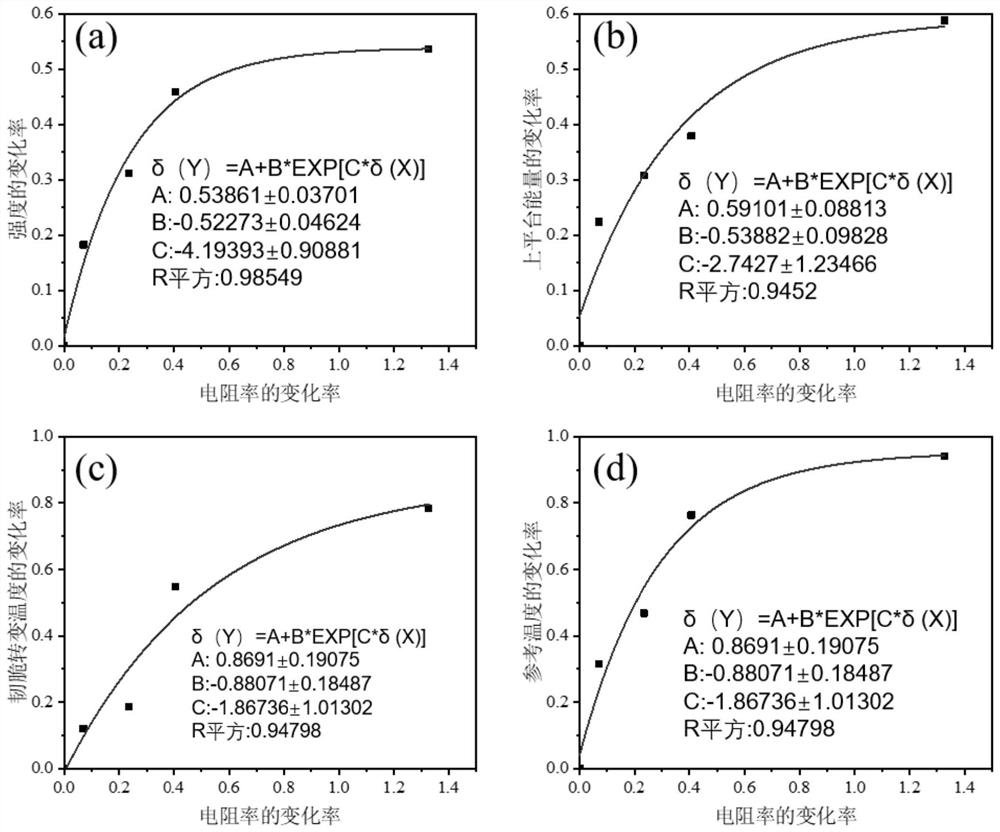
[0047] Embodiment 1: upper platform energy-resistivity

[0048] Depend on figure 1 (b) It can be seen that:

[0049] ΔUSE / USE 0 =0.59-0.54exp(-2.74Δρ / ρ 0 ) (4.1)

[0050] Where: ΔUSE = USE 0 -USE; Δρ = ρ - ρ 0

[0051] Explanation: During the irradiation embrittlement process of RPV steel, the platform energy of the material decreases gradually, so here define ΔUSE=USE 0 -USE.

[0052] The unit of USE is Joule, and the unit of ρ is ×10 -7 ohm meter.

[0053] For this research object RPV steel, USE 0 is 335J, ρ 0 is 3.03×10 -7 Ω·m, USE=137.01+2803.03exp(-0.90ρ) after being substituted into the above formula for calculation.

Embodiment 2

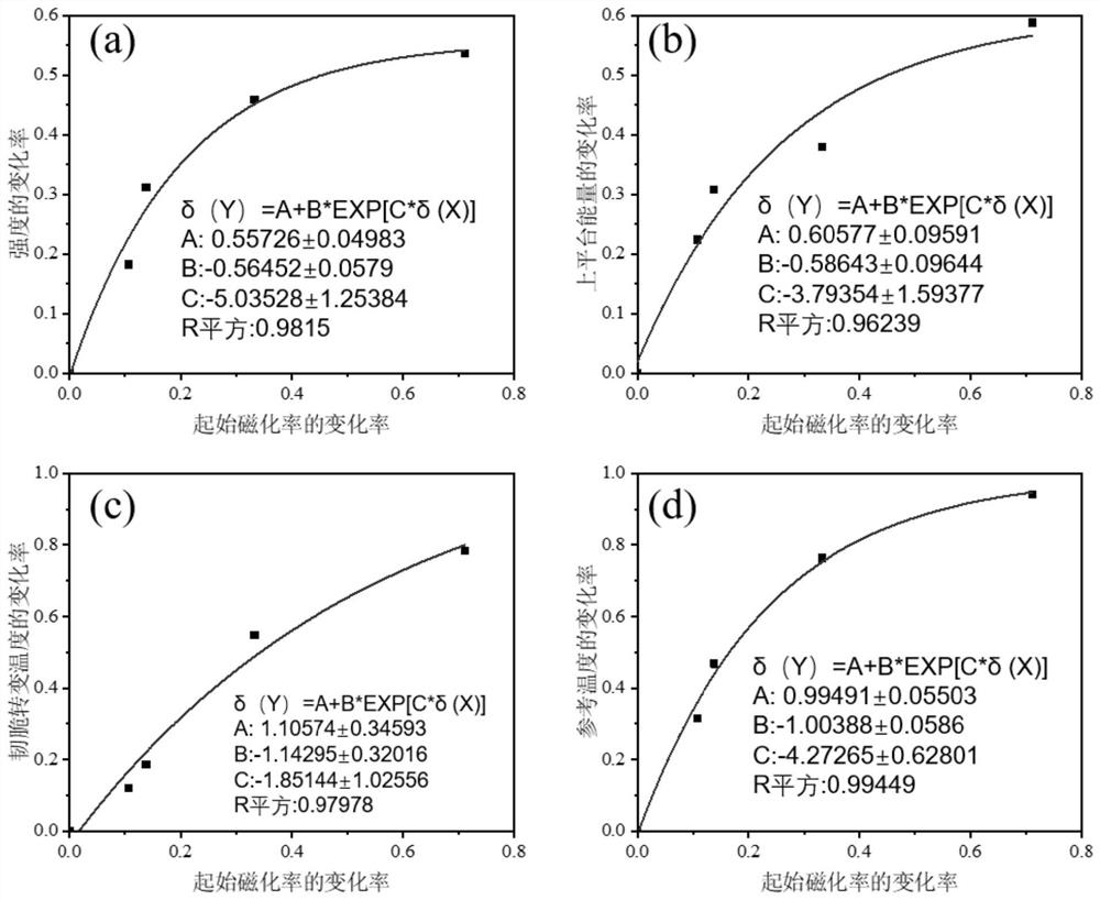
[0054] Example 2: Reference temperature - initial magnetic susceptibility

[0055] Depend on figure 2 (d) know that:

[0056] ΔT 0 / T 00 =0.99-1.00exp(-4.27Δχ / χ 0 ) (4.2)

[0057] where: ΔT 0 =T 0 –T 00 ;Δχ=χ 0 -χ.

[0058] Explanation: The material reference temperature increases gradually during the irradiation embrittlement process of RPV steel, so ΔT is defined here 0 =T 0 –T 00 ; while the initial magnetic susceptibility is gradually reduced, so define Δχ=χ 0 -χ.

[0059] T 0 The unit of is absolute temperature, and χ is dimensionless.

[0060] For the RPV steel of this research object, T 00 is 203K, χ 0 is 11.406, after substituting into the above formula to calculate T 0 =404.97-2.84exp(0.37χ).

Embodiment 3

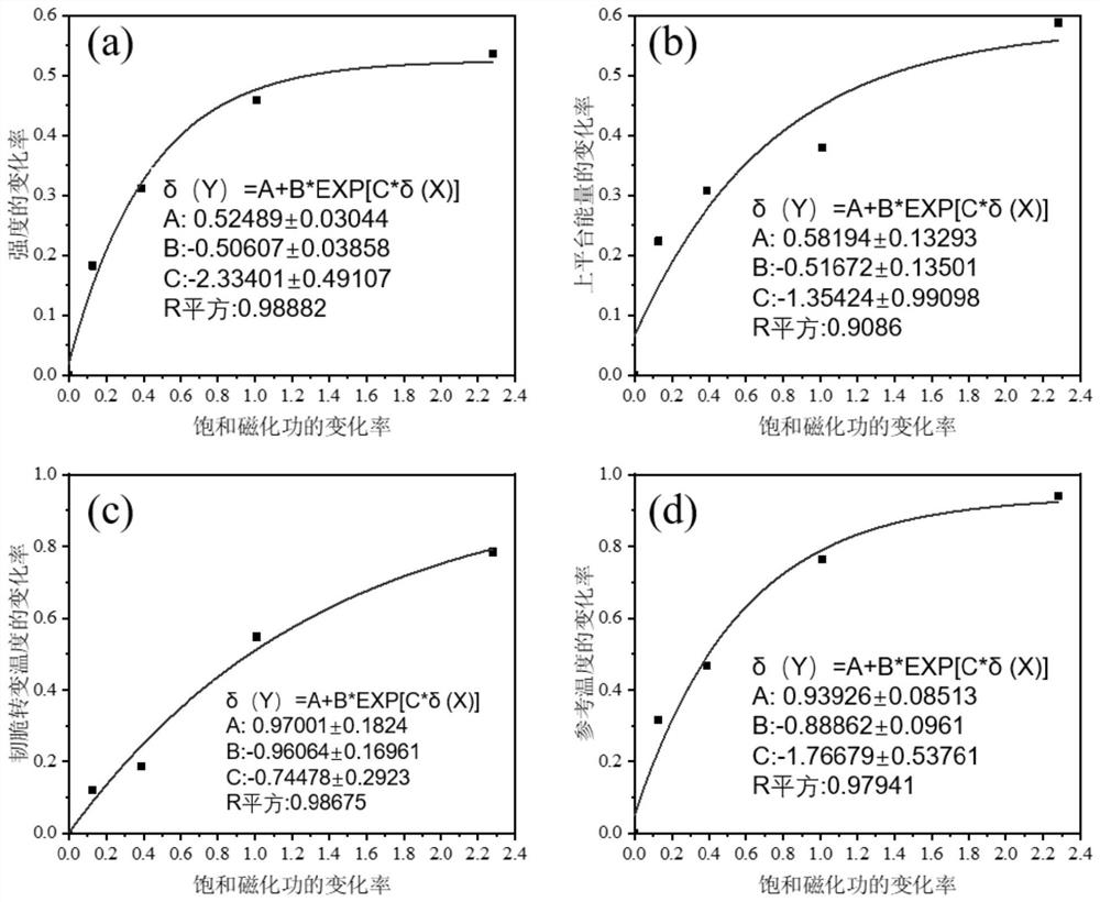
[0061] Example 3: Ductile-brittle transition temperature-saturation magnetization work

[0062] Depend on image 3 (c) know:

[0063] ΔRT NDT / RT NDT0 =0.94-0.89exp(-1.77ΔW / W 0 ) (4.3)

[0064] Where: ΔRT NDT =RT NDT -RT NDT0 ;ΔW=W-W 0 .

[0065] Explanation: During the irradiation embrittlement process of RPV steel, the ductile-brittle transition temperature of the material increases gradually, so here the definition of ΔRT NDT =RT NDT -RT NDT0 .

[0066] RT NDT The unit of is absolute temperature, and the unit of W is kilojoules / cubic meter.

[0067] For this research object RPV steel, RT NDT0 241K, W 0 246.3KJ / m 3 , after substituting into the above formula to calculate RT NDT =474.77-492.13exp(-0.0030W).

[0068] Table 4.1 Using the predictive unified model to characterize the fitting accuracy of the relationship model between the rate of change of mechanical properties and the rate of change of electromagnetic properties of reactor pressure vessel steel...


PUM


Abstract

The invention discloses a method for monitoring radiation embrittlement of reactor pressure vessels of nuclear power plants, which comprises the following steps: 1) Obtaining the electromagnetic performance parameter value X of the initial state of reactor pressure vessel steel 0 and mechanical property parameter value Y 0 ; 2) Real-time testing to obtain the electromagnetic performance parameter X of the reactor pressure vessel steel monitoring position at a specific time point after radiation embrittlement; and 3) According to the functional relationship δ(Y)=A+B*exp[C* δ(X)] to determine the mechanical performance parameter Y, wherein, the rate of change of electromagnetic properties δ(X)=|X‑X 0 | / X 0 , rate of change of mechanical properties δ(Y)=|Y‑Y 0 | / Y 0 , A, B, C are calculation coefficients. Compared with the prior art, the method for monitoring radiation embrittlement of nuclear power plant reactor pressure vessels can not only realize real-time and multiple non-destructive measurements, but also have accurate data, good test operation safety, and can simultaneously monitor multiple positions of the reactor pressure vessel degree of radiation embrittlement.

Description

technical field [0001] The invention belongs to the technical field of nuclear power, and more specifically, the invention relates to a method for monitoring radiation embrittlement of a reactor pressure vessel of a nuclear power plant. Background technique [0002] Nuclear safety is the premise and the highest principle of nuclear power development, and the radiation embrittlement of reactor pressure vessels is an important part of nuclear safety. The reactor pressure vessel is one of the most critical equipment of the nuclear steam supply system of the nuclear power plant. It is the only large-scale equipment that cannot be replaced in the whole life of the nuclear power plant. Its safe service life determines the operating life and economy of the nuclear power plant. The main function of the reactor pressure vessel is to support the core fuel assembly, control assembly, reactor internals and the steel pressure vessel containing the primary circuit coolant. It is the secon...

Claims


Application Information

Patent Timeline
Patent Type & Authority Patents(China)
IPC IPC(8): G21C17/003
CPCG21C17/003Y02E30/30
Inventor 李承亮束国刚刘伟谭珂赵建光段远刚
Owner 中广核工程有限公司
Why Eureka
Try Eureka