Road piezoelectric power generation deceleration strip

A piezoelectric power generation and speed bump technology, applied in bridge parts, bridges, buildings, etc., can solve the problems of low energy utilization rate, single piezoelectric energy conversion mode of speed bump, complex mechanical structure, etc. Simple structure and improved conversion efficiency

Active Publication Date: 2019-10-22
CHANGAN UNIV
View PDF8 Cites 4 Cited by
  • Summary
  • Abstract
  • Description
  • Claims
  • Application Information

AI Technical Summary

Problems solved by technology

[0003] In view of the deficiencies and defects of the prior art above, the purpose of the present invention is to provide a road-use piezoelectric power generation deceleration belt, which solves the technical problems of the existing deceleration belt with single piezoelectric energy conversion mode, complex mechanical structure and low energy utilization rate

Method used


Image

  • Road piezoelectric power generation deceleration strip
  • Road piezoelectric power generation deceleration strip
  • Road piezoelectric power generation deceleration strip

Examples


Embodiment

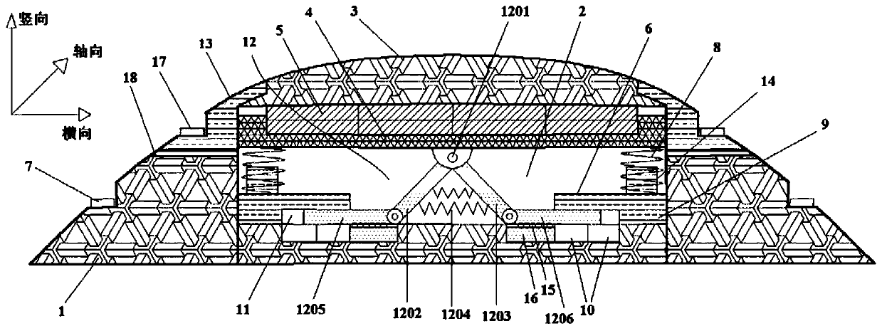
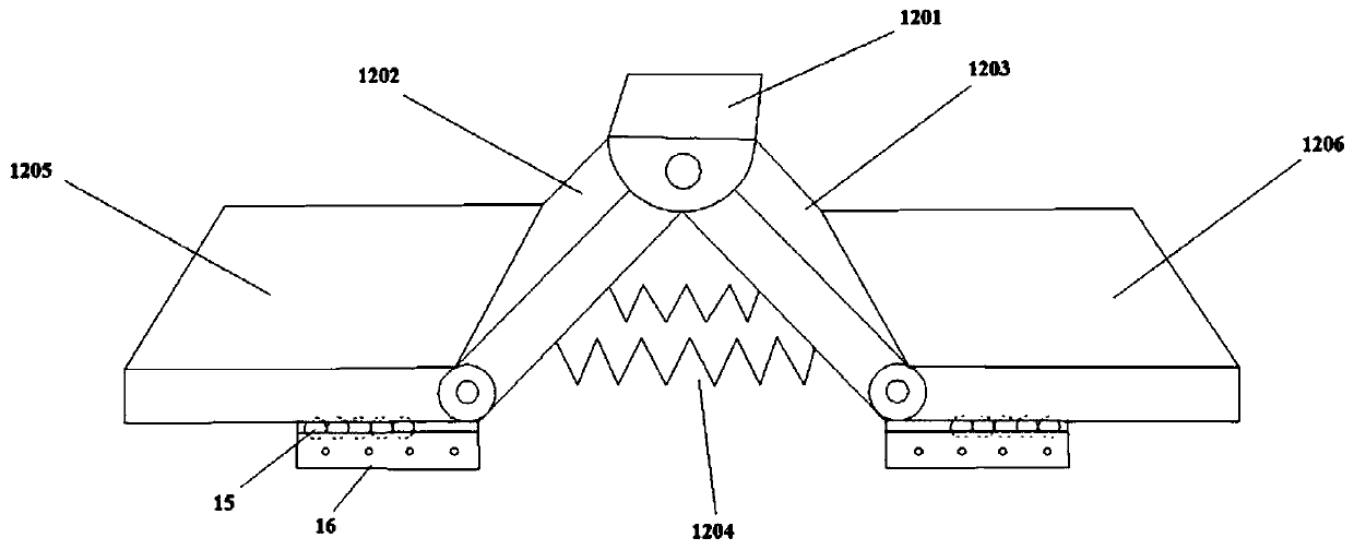
[0043] Following the above technical solution, this embodiment provides a road-use piezoelectric power generation deceleration belt, such as Figure 1 to Figure 6 As shown, including the base 1, the base 1 is provided with a cavity 2 with an open top, and the open top of the cavity 2 is provided with a pressure-bearing cover 3, and the pressure-bearing cover 3 can move vertically relative to the base 1;

[0044] A sinking-floating tray 4 is arranged in the cavity 2 below the pressure-bearing cover 3, and more than one layer of d is arranged between the sinking-floating tray 4 and the pressure-bearing cover 3 33 Piezoelectric energy harvesting sheet 5; the pressure-bearing cover 3 is pressed down vertically so that d 33 The piezoelectric energy harvesting sheet 5 is squeezed to generate electricity;

[0045] A cantilever support plate 6 is arranged on the vertical inner wall of the cavity 2 along the axial direction, and the bottom ends of a plurality of vertical return spring...


PUM


Abstract

The invention provides a road piezoelectric power generation deceleration strip. The road piezoelectric power generation deceleration strip comprises a base, a cavity with an open top is arranged in the base, a pressure bearing cover is arranged at the open top of the cavity, a sink and float type tray is arranged at the position, below the pressure bearing cover, in the cavity, one or more layersof d33 piezoelectric energy harvesting pieces are arranged between the sink and float type tray and the pressure bearing cover, the pressure bearing cover is vertically downwards pressed to enable the d33 piezoelectric energy harvesting pieces to be extruded for power generation, a cantilever supporting plate is arranged on the vertical inner wall of the cavity in the axial direction, d15 piezoelectric energy harvesting pieces are fixedly distributed on the portion, below the cantilever supporting plate and in the cavity, of the base in the axial direction correspondingly, a transverse shearcavity with the open inner side is formed among a supporting strip, the cantilever supporting plate and the d15 piezoelectric energy harvesting pieces, a force transmission mechanism is arranged at the position, at the center of the bottom of the sink and float type tray, in the cavity, and the pressure bearing cover vertically and downwards presses the force transmission mechanism, so that a first shear bottom plate and a second shear bottom plate move towards the two transverse sides to be in contact with the d15 piezoelectric energy harvesting pieces to generate shear force for power generation.

Description

technical field [0001] The invention belongs to the field of road engineering and relates to piezoelectric energy conversion technology, in particular to a road-use piezoelectric power generation speed bump. Background technique [0002] Speed ​​bumps are generally located at highway crossings, industrial and mining enterprises, schools, residential quarters, etc., where vehicles need to slow down or easily cause traffic accidents. They are special traffic safety facilities used to reduce driving speed. The mechanical vibration energy generated by the deceleration effect of the deceleration belt is considerable, and the energy loss is relatively serious. If the piezoelectric power generation technology can be used to convert the mechanical vibration energy into electrical energy, the excessive energy loss can be effectively avoided, and the current application of piezoelectric power generation technology There are few studies on road speed bumps. Therefore, it is necessary ...

Claims


Application Information

Patent Timeline
Patent Type & Authority Applications(China)
IPC IPC(8): E01D19/10
CPCE01D19/106
Inventor 王朝辉刘鲁清王帅赵永祯高志伟余功新舒诚樊振通
Owner CHANGAN UNIV
Why Eureka
Try Eureka