Cutting fluid suction head

A technology of cutting fluid and outer surface, which is applied in the direction of grinding/polishing equipment, grinding/polishing safety devices, metal processing machinery parts, etc. It can solve the problems of unfavorable use, lack of cleaning and maintenance of cutting fluid suction heads, etc., and achieve enhanced use effect, increase permeability, enhance connection effect

Pending Publication Date: 2020-04-28
苏州市精成悦机械有限公司
View PDF0 Cites 0 Cited by
  • Summary
  • Abstract
  • Description
  • Claims
  • Application Information

AI Technical Summary

Problems solved by technology

[0003] When the existing cutting fluid tips are installed and used, first of all, some cutting fluid tips lack a str

Method used


Image

  • Cutting fluid suction head
  • Cutting fluid suction head
  • Cutting fluid suction head

Examples


Embodiment Construction

[0023] In order to make the technical means, creative features, goals and effects achieved by the present invention easy to understand, the present invention will be further described below in conjunction with specific embodiments.

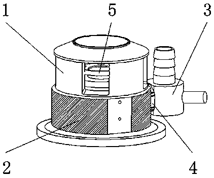
[0024] Such as Figure 1-6 As shown, the cutting fluid suction head includes a suction head main body 1, the inner surface of one side of the suction head main body 1 is provided with a running bearing 5, and the outer surface of the lower end of the suction head main body 1 is provided with a cleaning mechanism 2, and one part of the cleaning mechanism 2 A connection ring 4 is provided on the side outer surface, and a connection mechanism 3 is provided on one side outer surface of the connection ring 4 .

[0025] Further, the interior of the cleaning mechanism 2 includes a base 21, a nano-processing cleaning coating 22, a cleaning plate 23, a storage tank 24, and a storage plate 25. The cleaning plate 23 is located at the front end of the base 21...


PUM


Abstract

The invention discloses a cutting fluid suction head comprising a suction head body. An operation bearing is arranged on the surface of the inner surface of one side of the suction head body. A cleaning mechanism is arranged on the outer surface of the lower end of the suction head body. A connection ring is arranged on the outer surface of one side of the cleaning mechanism. A connection mechanism is arranged on the outer surface of one side of the connection ring. According to the cutting fluid suction head, by means of the cleaning mechanism, the cleaning mechanism can provide a convenientdaily cleaning and maintaining structure in the work process, workers can conveniently conduct the maintaining work of the suction head while the cleaning function is provided, the use effect is enhanced, the cleaning efficiency is also improved, and use is facilitated for people; and by means of a connection mechanism, the connection mechanism provides a simple and practical connection structure,the connection function can be provided in the work process, conveying pipes can be conveniently connected, and the use effect of the device is further improved.

Description

technical field [0001] The invention relates to the field of cutting fluid filtration, in particular to a cutting fluid suction head. Background technique [0002] The lubricating effect of the cutting fluid during the cutting process can reduce the friction between the rake face and the chip, the flank face and the machined surface, and form a part of the lubricating film, thereby reducing the cutting force, friction and power consumption, and reducing the friction between the tool and the workpiece. The surface temperature of the friction part of the blank and the wear of the tool can improve the cutting performance of the workpiece material. During the grinding process, after adding the grinding fluid, the grinding fluid penetrates into the grinding wheel abrasive grain-workpiece and abrasive grain-grinding debris to form a lubricating film , to reduce the friction between the interfaces, prevent abrasive cutting edge wear and adhesion of chips, thereby reducing grinding ...

Claims


Application Information

Patent Timeline
IPC IPC(8): B24B55/03B23Q11/10
CPCB23Q11/10B24B55/03
Inventor 缪伟梁
Owner 苏州市精成悦机械有限公司
Why Eureka
Try Eureka