An automatic guidance method for micro-workpiece measurement

An automatic guidance and workpiece technology, applied in the field of measurement and imaging, can solve the problems of difficult to complete high-precision guidance, small size of miniature workpieces, and low efficiency

Active Publication Date: 2021-02-05
HEFEI UNIV OF TECH
View PDF13 Cites 2 Cited by
  • Summary
  • Abstract
  • Description
  • Claims
  • Application Information

AI Technical Summary

Problems solved by technology

[0005] 1. The initial visual guidance is to manually use the camera to take images, and guide the probe ball head to the measurement position according to the image; subsequent improvements have enabled the operator to manually select the workpiece to be tested and the probe ball head on the image, so that the probe ball The needle ball head automatically moves to the measurement position, but the methods before and after the improvement have the problem of low efficiency;
[0006] 2. The existing visual guidance method needs to calibrate the camera before each use, and the time consumed by the calibration process far exceeds the time consumed by the guidance process
[0007] 3. In the existing methods, after the vision system is calibrated, the focal length and camera position cannot be changed. However, due to the extremely small size of the micro-workpiece, it is difficult to complete high-precision guidance for the original image of the unenlarged workpiece.

Method used


Image

  • An automatic guidance method for micro-workpiece measurement
  • An automatic guidance method for micro-workpiece measurement
  • An automatic guidance method for micro-workpiece measurement

Examples


Embodiment Construction

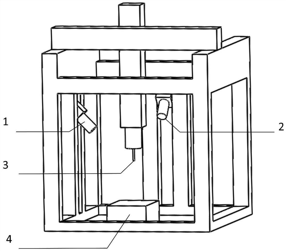
[0077] see figure 1 , in this embodiment, the automatic guidance method for micro-workpiece measurement is to use a three-coordinate measuring machine. In the measuring machine, the probe ball head 3 is guided to the measurement position for measurement by visual guidance; the measurement position refers to: the workpiece category It is divided into hole-type workpieces and non-hole-type workpieces. For the measurement of hole-type workpieces, the probe ball head 3 is guided to the threshold range of the center point of the workpiece hole to be measured. For the measurement of non-hole-type workpieces, the probe ball The head 3 is guided to within the threshold range of the center point of the upper surface of the workpiece to be measured.

[0078] like figure 1 As shown, the vision system is set on the base of the measuring machine, including: two cameras are fixedly installed, the two cameras are of the same model, and the front end is equipped with an auto-focus lens. The ...


PUM


Abstract

The invention discloses a micro workpiece measurement-oriented automatic guiding method. According to the micro workpiece measurement-oriented automatic guiding method, two cameras fixed on a three-coordinate measuring machine base is utilized to photograph a to-be-measured workpiece and a probe ball head so as to obtain a left view image and a back view image; the to-be-detected workpiece in theimages shot by the two cameras is searched and identified; the to-be-detected workpiece can be classified as a hole-type workpiece, or a non-hole type workpiece; a position relationship between the to-be-detected workpiece and the probe ball head is calculated; the probe ball head is guided to move along an X axis, a Y axis and a Z axis, so that the probe ball head moves to the to-be-detected workpiece; and the probe ball head is guided to be a position near a measurement position through initial guide; after the focal lengths of the lenses of the cameras change, the probe ball head is guidedto be the measurement position through accurate guide.

Description

technical field [0001] The invention relates to the fields of measurement and imaging, and in particular to a fully automatic guiding method suitable for measuring with a three-coordinate measuring machine and using a contact probe to measure micro-hole workpieces and non-hole workpieces. Background technique [0002] In the prior art, methods such as structured light, laser interference, and laser triangulation are used to measure micro-workpieces. However, it is difficult to measure holes with high aspect ratios using the above methods; when the above methods are used to measure non-hole workpieces, Its measurement accuracy is lower than that of contact measurement; at the same time, the cost of measurement methods of structured light and laser interference is relatively high. [0003] The use of contact measuring probes to measure micro-hole workpieces not only meets the requirements for measurement accuracy, but also measures relevant parameters of hole workpieces at dif...

Claims


Application Information

Patent Timeline
Patent Type & Authority Patents(China)
IPC IPC(8): G01B21/04G01B21/20
CPCG01B21/047G01B21/20
Inventor 程真英栾赫郑杰李瑞君
Owner HEFEI UNIV OF TECH
Why Eureka
Try Eureka