

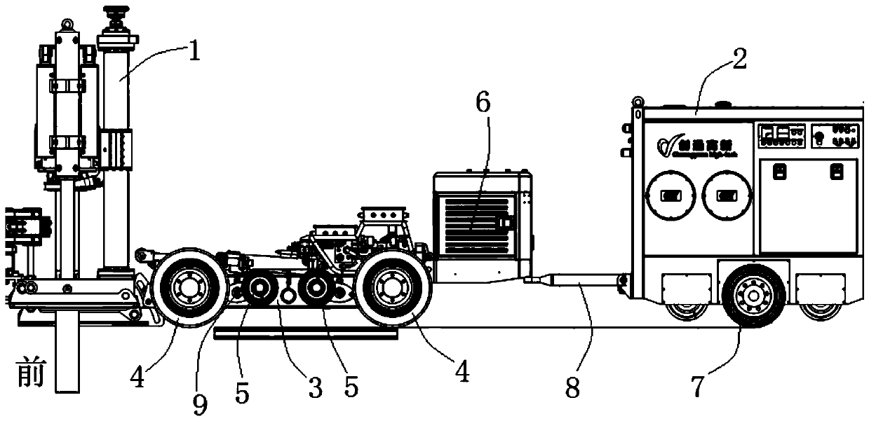
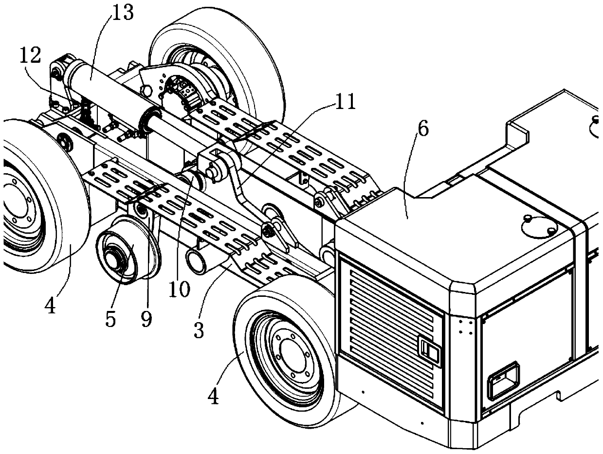
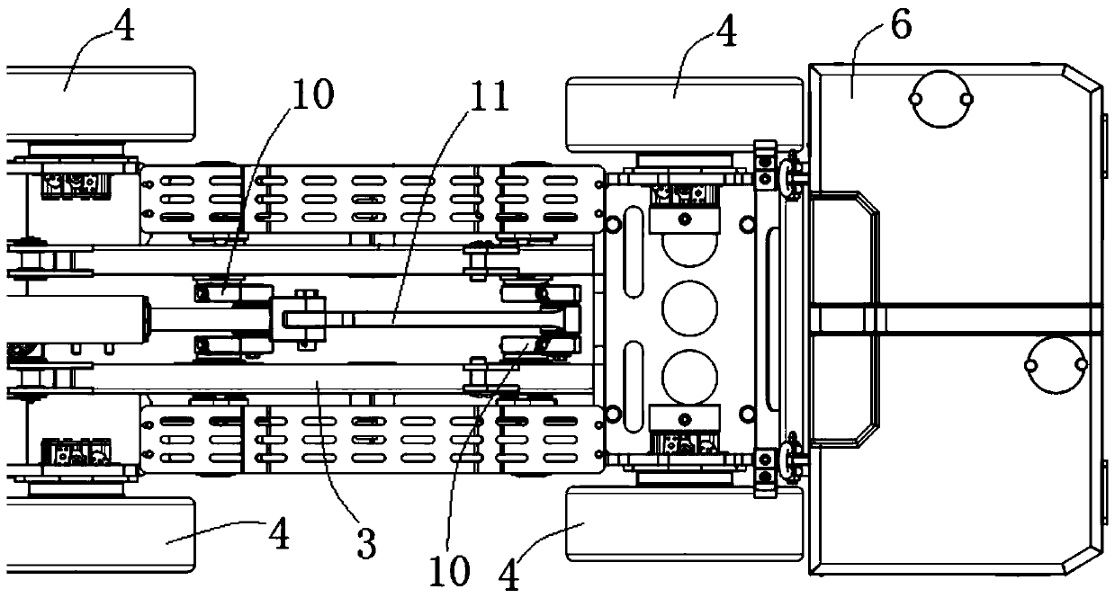
Movable raise boring machine capable of rapidly switching rail wheels and tires
A technology for quick switching and raising drilling rigs, applied in the field of mining machinery, can solve the problems of inconvenient transportation and transfer of drilling rigs, and achieve the effects of fast and convenient switching, stable transmission, and convenient and direct operation
- Summary
- Abstract
- Description
- Claims
- Application Information
AI Technical Summary
Problems solved by technology
Method used
Image

Examples
Embodiment Construction
[0036] The following will clearly and completely describe the technical solutions in the embodiments of the present invention with reference to the accompanying drawings in the embodiments of the present invention. Obviously, the described embodiments are only part of the embodiments of the present invention, not all of them. Based on the embodiments of the present invention, all other embodiments obtained by persons of ordinary skill in the art without creative efforts fall within the protection scope of the present invention.
[0037] It should be noted that all directional indications (such as up, down, left, right, front, back...) in the embodiments of the present invention are only used to explain the relationship between the components in a certain posture (as shown in the accompanying drawings). Relative positional relationship, movement conditions, etc., if the specific posture changes, the directional indication will also change accordingly.
[0038] In addition, in the...
PUM
 Abstract
Description
Claims
Application Information