Supercharge Your Innovation With Domain-Expert AI Agents!

An intake manifold with a built-in intercooler

A technology of intercooler and intercooler, which is applied in the field of intake manifold with built-in intercooler, which can solve the problems of increasing the temperature of the horizontal bar, reducing the working efficiency of the intercooler, increasing the number of accessories and assembly time, etc., and achieving the elimination of installation seal The process of circle, prolonging the service life of products, reducing the effect of total assembly time

Active Publication Date: 2022-04-08
索格菲(苏州)汽车部件有限公司
View PDF0 Cites 0 Cited by
  • Summary
  • Abstract
  • Description
  • Claims
  • Application Information

AI Technical Summary

Problems solved by technology

[0002] The turbocharger is driven by the exhaust gas from the engine. The turbocharger is in a high temperature state, and the temperature of the intake air passing through the turbocharger will increase. Therefore, the turbocharged engine needs to use an intercooler to reduce the intake air temperature. , the intercooler is installed inside the intake manifold, since the intake air is in a state of high temperature and high pressure, the sealing performance between the intercooler and the intake manifold directly affects the cooling efficiency of the intake air; see figure 1 , the existing intercooler is equipped with a sealing ring along the lower part, and the intercooler is installed in the intake manifold to achieve a sealing effect, but the process of installing the sealing ring is cumbersome, which virtually reduces the production efficiency; Moreover, after the existing intercooler is installed in the intake manifold, if there is a gap between the core of the intercooler and the inner wall of the intake manifold, part of the intake air will enter the air passage through the gap and eventually cause the temperature of the horizontal bar to increase. The gap with the inner wall of the intake manifold is small enough. In the prior art, the intercooler is fixed inside the manifold by adding several through bolts, but there are the following disadvantages: the wind resistance of the air flowing through the intercooler is increased , reducing the effective heat dissipation area, reducing the working efficiency of the intercooler, increasing the number of accessories and assembly time, resulting in an increase in product manufacturing costs, additional mounting holes need to be opened on the manifold shell, resulting in increased leakage risk

Method used


Image

  • An intake manifold with a built-in intercooler
  • An intake manifold with a built-in intercooler
  • An intake manifold with a built-in intercooler

Examples


Embodiment Construction

[0021] The preferred embodiments of the present invention will be described in detail below in conjunction with the accompanying drawings, so that the advantages and features of the present invention can be more easily understood by those skilled in the art, so as to define the protection scope of the present invention more clearly.

[0022] see Figure 2 to Figure 9 , the embodiment of the present invention includes:

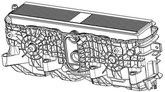
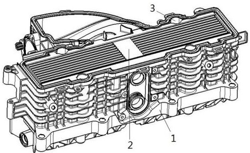
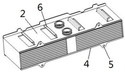
[0023] An intake manifold with a built-in intercooler, comprising: a manifold body 1 and an intercooler 2, the manifold body 1 is provided with a plenum chamber 7, and the intercooler 2 is inserted and installed from the upper side of the plenum chamber 7 in the plenum chamber. The top edge of the intercooler 2 is provided with a circle of upper edge sealing, and the bottom edge of the intercooler 2 is provided with a circle of outwardly protruding flanges 4; Step surface 8, when the intercooler is installed in the pressure stabilizing chamber, the flanging i...


PUM


Abstract

The invention discloses an intake manifold with a built-in intercooler, which comprises: a manifold body and an intercooler; side; the bottom of the plenum corresponding to the flange of the intercooler is provided with a circle of stepped surfaces, and a circle of small bosses are provided on the stepped surface; on both sides of the intercooler are provided a number of claws protruding toward the outside of the intercooler. It is "L" shaped, with two groups of claws on each side, and the directions of the two groups of claws are opposite. Matching, the card slot extends downward from the top of the plenum chamber. Through the above method, the present invention can increase the side installation strength of the intercooler, effectively maintain the stability of the intercooler's own structure, thereby prolonging the service life of the product; it can reduce the cost of materials, cancel the process of installing the sealing ring, and reduce the overall cost. Assembly time is reduced, which indirectly improves production efficiency.

Description

technical field [0001] The invention relates to the field of intake manifolds, in particular to an intake manifold with a built-in intercooler. Background technique [0002] The turbocharger is driven by the exhaust gas from the engine. The turbocharger is in a high temperature state, and the temperature of the intake air passing through the turbocharger will increase. Therefore, the turbocharged engine needs to use an intercooler to reduce the intake air temperature. , the intercooler is installed inside the intake manifold, since the intake air is in a state of high temperature and high pressure, the sealing performance between the intercooler and the intake manifold directly affects the cooling efficiency of the intake air; see figure 1 , the existing intercooler is equipped with a sealing ring along the lower part, and the intercooler is installed in the intake manifold to achieve a sealing effect, but the process of installing the sealing ring is cumbersome, which virtu...

Claims


Application Information

Patent Timeline
Patent Type & Authority Patents(China)
IPC IPC(8): F02M35/104F02B29/04
CPCF02M35/10268F02M35/104F02B29/0406Y02T10/12
Inventor 沃德里·吉恩·保尔徐海锋
Owner 索格菲(苏州)汽车部件有限公司
Features
  • R&D
  • Intellectual Property
  • Life Sciences
  • Materials
  • Tech Scout
  • Unparalleled Data Quality
  • Higher Quality Content
  • 60% Fewer Hallucinations
Learn More