
Telescopic electricity taking rail

A telescopic and track technology, applied in the field of lighting, can solve the problems of increasing the workload of wire management and affecting the appearance, and achieve the effect of avoiding troublesome problems in wire management, convenient operation, and neat and beautiful installation.

Pending Publication Date: 2019-10-25
SELF ELECTRONICS CO LTD
View PDF0 Cites 1 Cited by
  • Summary
  • Abstract
  • Description
  • Claims
  • Application Information

AI Technical Summary

Problems solved by technology

[0003] In the prior art, the width of the shelf laminates will be adjusted frequently, which will cause the installation position of the lamps to change accordingly, and then the length of the wires will also have to be adjusted to meet the requirements of the installation position of the lamps, which will increase the workload of cable management. ; At the same time, because the power supply wires of the existing design are exposed, a certain length needs to be reserved during installation for subsequent adjustment and utilization, which affects the appearance

Method used


Image

  • Telescopic electricity taking rail
  • Telescopic electricity taking rail
  • Telescopic electricity taking rail

Examples


Embodiment Construction

[0026] Embodiments of the present invention are described in detail below, examples of which are shown in the drawings, wherein the same or similar reference numerals designate the same or similar elements or elements having the same or similar functions throughout. The embodiments described below by referring to the figures are exemplary only for explaining the present invention and should not be construed as limiting the present invention.

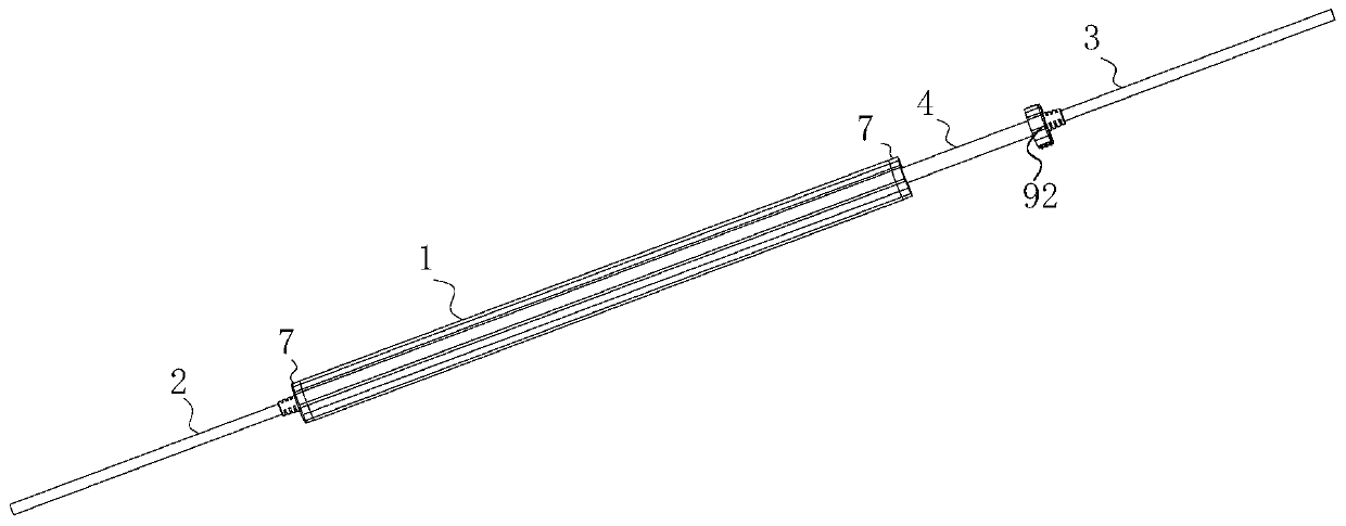
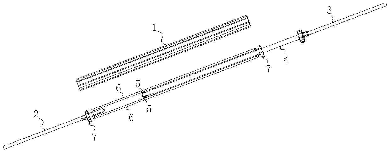
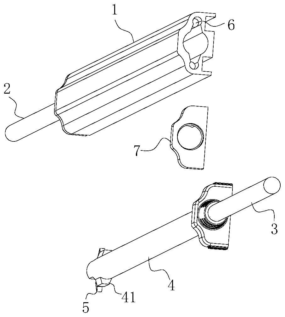
[0027] Such as Figures 1 to 6 Shown is a schematic structural diagram of an embodiment of the present invention, the telescopic power-taking track includes a strip-shaped housing 1 with a hollow cavity and a sliding device with one end extending into the cavity of the strip-shaped housing 1 and slidingly connected with the housing 1; the housing 1. One end is provided with an input wire 2 and the other end is provided with an output wire 3. The sliding device is electrically connected to the input wire 2 and the output wire 3 respective...


PUM


Abstract

The invention relates to a telescopic electricity taking rail. The telescopic electricity taking rail comprises a strip-shaped shell (1) with a hollow cavity, and a sliding device with one end extending into the cavity and connected with the shell (1) in a sliding mode; and one end of the shell (1) is provided with an input wire (2), and the other end of the shell (1) is provided with an output wire (3), the sliding device is electrically connected with the input wire (2) and the output wire (3), and when the sliding device slides in the length direction of the shell (1), the extending lengthof the output wire (3) relative to the shell (1) is correspondingly changed. By adopting the design, the sliding device of the electricity taking rail is adjusted, and the extending length of the output wire relative to the shell can be correspondingly changed, so that the requirement for different lengths of a power supply wire is met, the operation is very convenient, and the appearance is attractive.

Description

technical field [0001] The invention relates to the technical field of lighting, in particular to a telescopic power-taking track. Background technique [0002] When installing lamps on shelf shelves in supermarkets, shopping malls and other occasions, the power supply wires need to be led out from the back of the shelves and then routed along the side brackets below the shelves and then connected to the lamps. board bracket. [0003] In the prior art, the width of the shelf laminates will be adjusted frequently, which will cause the installation position of the lamps to change accordingly, and then the length of the wires will also have to be adjusted to meet the requirements of the installation position of the lamps, which will increase the workload of cable management. ; Simultaneously, because the power supply wire of existing design is exposed outside, need to reserve certain length during installation so that follow-up adjustment utilizes, and influences attractive in...

Claims


Application Information

Patent Timeline
IPC IPC(8): F21V33/00F21V27/00H01R13/73H01R13/03H01R13/52
CPCF21V33/00F21V27/00H01R13/73H01R13/03H01R13/52H01R2103/00H01R25/142H01R11/11
Inventor 房磊
Owner SELF ELECTRONICS CO LTD
Learn More