Mouse nerve retrograde tracing mark component

A nerve and mouse technology, applied in the field of neurobiological science experiments, can solve the problems of difficult operation, large differences in the number of labels, and reduce the number of experimental mice, and achieve the effect of preventing relative displacement.

A nerve and mouse technology, applied in the field of neurobiological science experiments, can solve the problems of difficult operation, large differences in the number of labels, and reduce the number of experimental mice, and achieve the effect of preventing relative displacement.

CN110376046APending Publication Date: 2019-10-25PEOPLES HOSPITAL PEKING UNIV

Image

  • Mouse nerve retrograde tracing mark component
  • Mouse nerve retrograde tracing mark component
  • Mouse nerve retrograde tracing mark component

Examples


Embodiment Construction

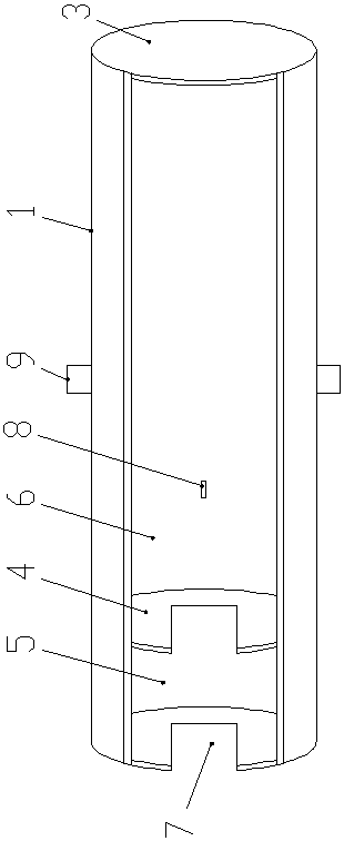
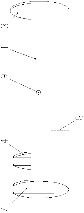
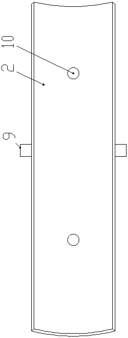
[0016] Such as Figure 1-3 As shown, the mouse nerve retrograde tracer assembly of the present invention includes a cylindrical tank body 1 and an upper cover 2, the shape of the cylindrical tank body 1 is cylindrical, and the cross section of the cylindrical tank body 1 is a superior arc. The cover 2 is an arc-shaped plate and its cross-section is inferior arc. The upper cover 2 is fastened on the cylindrical tank body 1. The upper cover 2 and the cylindrical tank body 1 form a complete cylindrical shape. The front and rear ends of the cylindrical tank body 1 A circular blocking plate 3 is respectively fixed, and a circular partition 4 is fixed in front of the cylindrical tank body 1, and the partition plate 4 divides the inner cavity of the cylindrical tank body 1 into a storage tank 5 on the front side and a storage tank on the rear side. Groove 6, placement groove 5 is used to place nerves and vaseline, storage tank 6 is the main tank body, and is used to store dyes. There...


PUM

PropertyMeasurementUnit
lengthaaaaaaaaaa
diameteraaaaaaaaaa

Abstract

A mouse nerve retrograde tracing mark component comprises a cylinder tank body and an upper cover. A shape of the cylinder tank body is a cylindrical shape, a cross section of the cylinder tank body is a major arc, an upper cover is a curved plate and the cross section is an inferior arc, the upper cover fastens the cylinder tank body, and the upper cover and the cylinder tank body form a completecylindrical shape. Single and multiple retrograde tracing marking of mouse nerves can be realized so that direct observation of a mutual relation between different sources of motor neuron pools or neuronal subgroups in a spinal cord becomes possible.

Description

technical field [0001] The invention belongs to the technical field of neurobiological science experiments, and in particular relates to a mouse nerve retrograde trace marker component. Background technique [0002] Neuroretrograde tracing is a common technique in neurobiological research, which can be used to determine the origin, quantity and distribution of neuronal somata projecting to specific target areas. There are many labeling methods for nerve retrograde tracing, including: soaking the nerve stump in a tracer (ie, dye), or injecting the dye directly into the nerve trunk or target muscle. However, intramuscular injection of the dye using either the neural stem or the target results in less efficient labeling of neurons and greater variability in the amount of labeling. In addition, nerve stump soaking methods, such as the traditional small pool method and the recently appeared silica gel cap method, the small pool method and the silica gel cap method are described ...

Claims


Application Information

Patent Timeline
25 Oct 2019
Publication
CN110376046A
IPC
G01N1/31
CPC
G01N1/31
Inventors
ι™ˆεš; ηŽ‹ε€©ε…΅