Vehicle controller of a vehicle power transmission device

a technology of transmission device and vehicle controller, which is applied in the direction of engine controller, machine/engine, mechanical apparatus, etc., can solve the problems of reducing engine output, difficult to carry out pre-reduction control in a suitable amount to meet the operating conditions, and changing gears produces large shocks, etc., to achieve easy adjustment of gears, easy to adjust, and easy to adjust the

Inactive Publication Date: 2007-07-26
ISUZU MOTORS LTD
View PDF8 Cites 7 Cited by
  • Summary
  • Abstract
  • Description
  • Claims
  • Application Information

AI Technical Summary

Benefits of technology

[0016] In dealing with a vehicle power transmission device equipped with an automatic clutch, it is a basic problem of the present invention to quickly change the gear by suppressing an increase in the engine rotational speed that results from the disconnection of the automatic clutch at the time of changing the gear for shifting up to avoid the flare and by bringing the engine rotational speed into agreement with the rotational speed of the transmission input shaft in an early time. At the time of changing the gear for shifting up, the invention suitably sets a target value for decreasing the engine output depending upon the operating conditions of the vehicle prior to disconnecting the clutch in order to prevent the occurrence of flare in all gears while suitably relaxing the “acceleration spoiling”.

Problems solved by technology

When the gear is changed while the vehicle is in operation using a low gear, a great decrease in the engine output by the pre-reduction control brings about the same result as the “acceleration spoiling”, and changing the gear produces a large shock due to the pre-reduction control.
According to the technology disclosed in the above JP-A-60-11757, the throttle is returned back in a constant amount for decreasing the engine output, still making it difficult to carry out the pre-reduction control in a suitable amount to meet the operating conditions.

Method used


Image

  • Vehicle controller of a vehicle power transmission device
  • Vehicle controller of a vehicle power transmission device
  • Vehicle controller of a vehicle power transmission device

Examples


Embodiment Construction

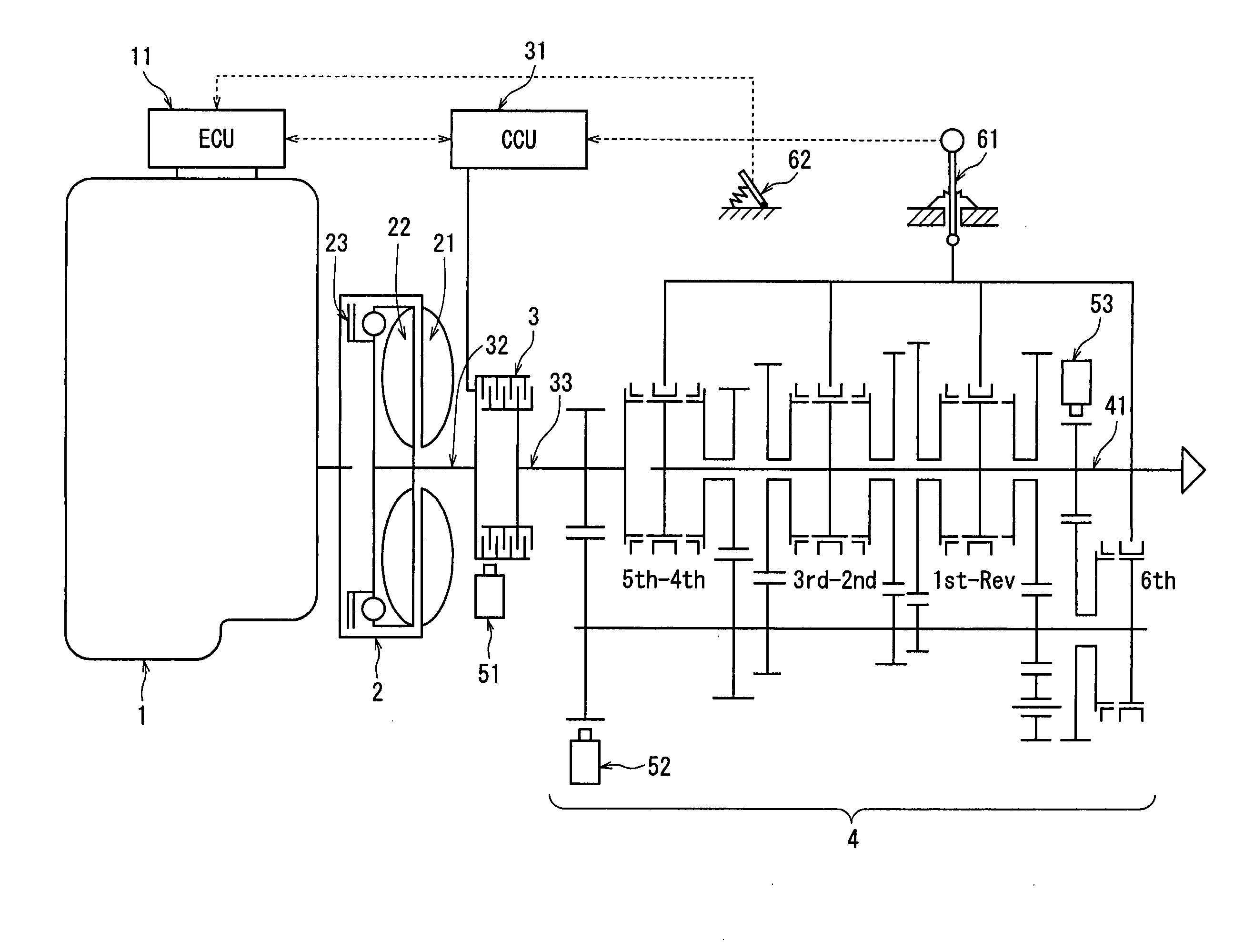
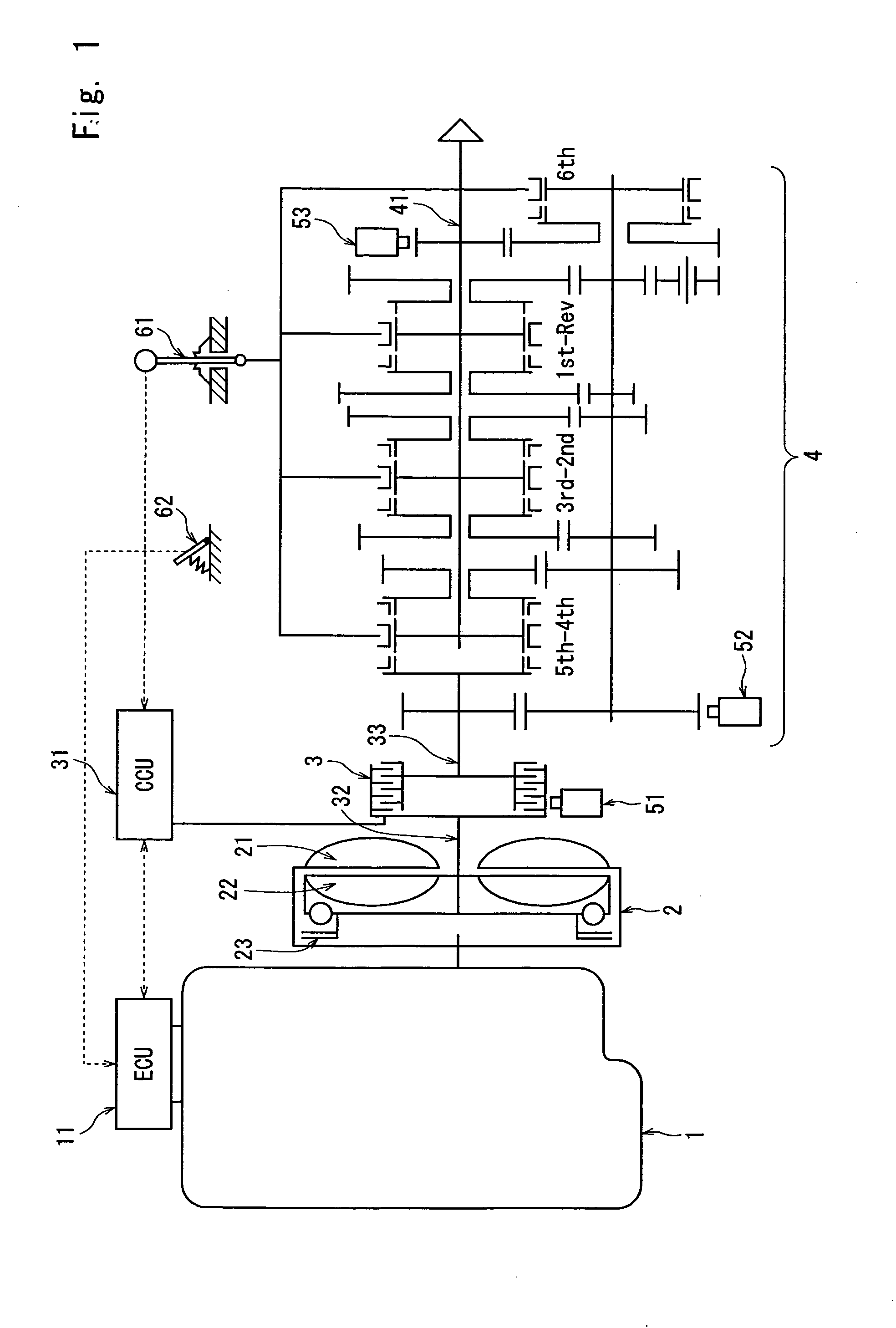
[0033] Described below with reference to the drawings is a controller in a vehicle power transmission device according to the present invention. Equipment constituting the vehicle power transmission device to which the invention is applied are not particularly different from those of the conventional device shown in FIG. 1. That is, in the power transmission device, a fluid coupling 2 is linked at the back of a diesel engine 1 and a transmission 4 having a parallel axis gear mechanism is further linked thereto via a wet multi-plate clutch 3 which is a clutch for automatically accomplishing connection and disconnection. A pump 21 and a turbine 22 of the fluid coupling 2 are coupled together by a lockup clutch 23 except when the vehicle is going to start and, thus, the output shaft of the diesel engine 1 is directly coupled to the input shaft 31 of the wet multi-plate clutch 3.

[0034] Further, the diesel engine 1 is equipped with an engine controller 11 and the wet multi-plate clutch ...


PUM


Abstract

In a vehicle power transmission device equipped with an automatic clutch, the gear-change for shifting up is effected suppressing a sudden increase in the engine rotational speed that results when the automatic clutch is disconnected, preventing deterioration in the drive feeling caused by the change of gear such as a shock due to the change of gear. At the time of changing the gear for shifting up, an engine controller (11) executes a pre-reduction control for decreasing the output of the engine 1 for a predetermined period of time prior to disconnecting the clutch (3). Since the engine output has been decreased, the rotational speed of the engine (1) does not suddenly rise despite the vehicle traveling load is removed as a result of disconnecting the clutch 3. A target value for decreasing the engine output is suitably set depending upon the vehicle operating conditions, and a sudden increase in the rotational speed is prevented in all gears while relaxing the shock of gear-change caused by a sharp change in the acceleration.

Description

TECHNICAL FIELD [0001] The present invention relates to a vehicle controller of a vehicle power transmission device which includes an automatic clutch between an engine and a transmission, the clutch being automatically connected and disconnected at the time of changing the gear by shifting a gear of the transmission depending upon the traveling conditions of the vehicle. BACKGROUND ART [0002] A variety kinds of vehicle power transmission devices for easy driving have been developed in an attempt to facilitate the driving of vehicles and to reduce fatigue to the drivers, and have been employed for the vehicles placed in the market. One of them may be an easy-to-drive device which uses a transmission of the type of a parallel axis gear mechanism similar to that of a so-called manual vehicle combined with an automatic clutch, so that the clutch can be automatically connected or disconnected at the time when the driver attempts to change the gear by shifting the gear by means of a gear...

Claims


Application Information

Patent Timeline
Patent Type & Authority Applications(United States)
IPC IPC(8): B60W10/00B60W10/04B60W10/02B60W10/06F02D29/00F02D29/02
CPCB60W10/02B60W10/06Y10T477/6407B60W30/19F02D29/02B60W10/11
Inventor HAYASHI, MASAHIKO
Owner ISUZU MOTORS LTD
Why Eureka
Try Eureka