Turbine engine and control method

a technology of turbine engines and control methods, applied in the direction of engines, efficient propulsion technologies, mechanical equipment, etc., can solve the problems of dangerous running away of second turbines, requiring major technical compromises, and setting a maximum threshold for the speed of rotation of the second rotary shaft requires significant overdimensioning,

Active Publication Date: 2016-10-13
SAFRAN HELICOPTER ENGINES
View PDF3 Cites 18 Cited by
  • Summary
  • Abstract
  • Description
  • Claims
  • Application Information

AI Technical Summary

Benefits of technology

[0007]The present invention seeks to remedy those drawbacks. In particular, the present description seeks to propose a method of regulating a turbine engine that makes it possible to avoid its free turbine running away dangerously in th...

Problems solved by technology

In this field, and more particularly for aircraft turboshaft engines and turboprops, and in particular for turboshaft engines that are to drive rotary wings, an accidental break in the power transmission from the second turbine, or “free” turbine, can lead to the second turbine running away dangerously.
Setting this maximum threshold nevertheless requires major technical compromises.
Nevertheless, a high maximum threshold for the speed of rotation of the second rotary shaft also requires significant overdimensioning of the second turbine and of the second rotary shaft compared with th...

Method used


Image

  • Turbine engine and control method
  • Turbine engine and control method
  • Turbine engine and control method

Examples


Embodiment Construction

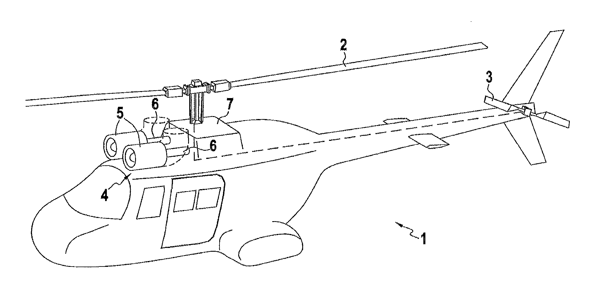
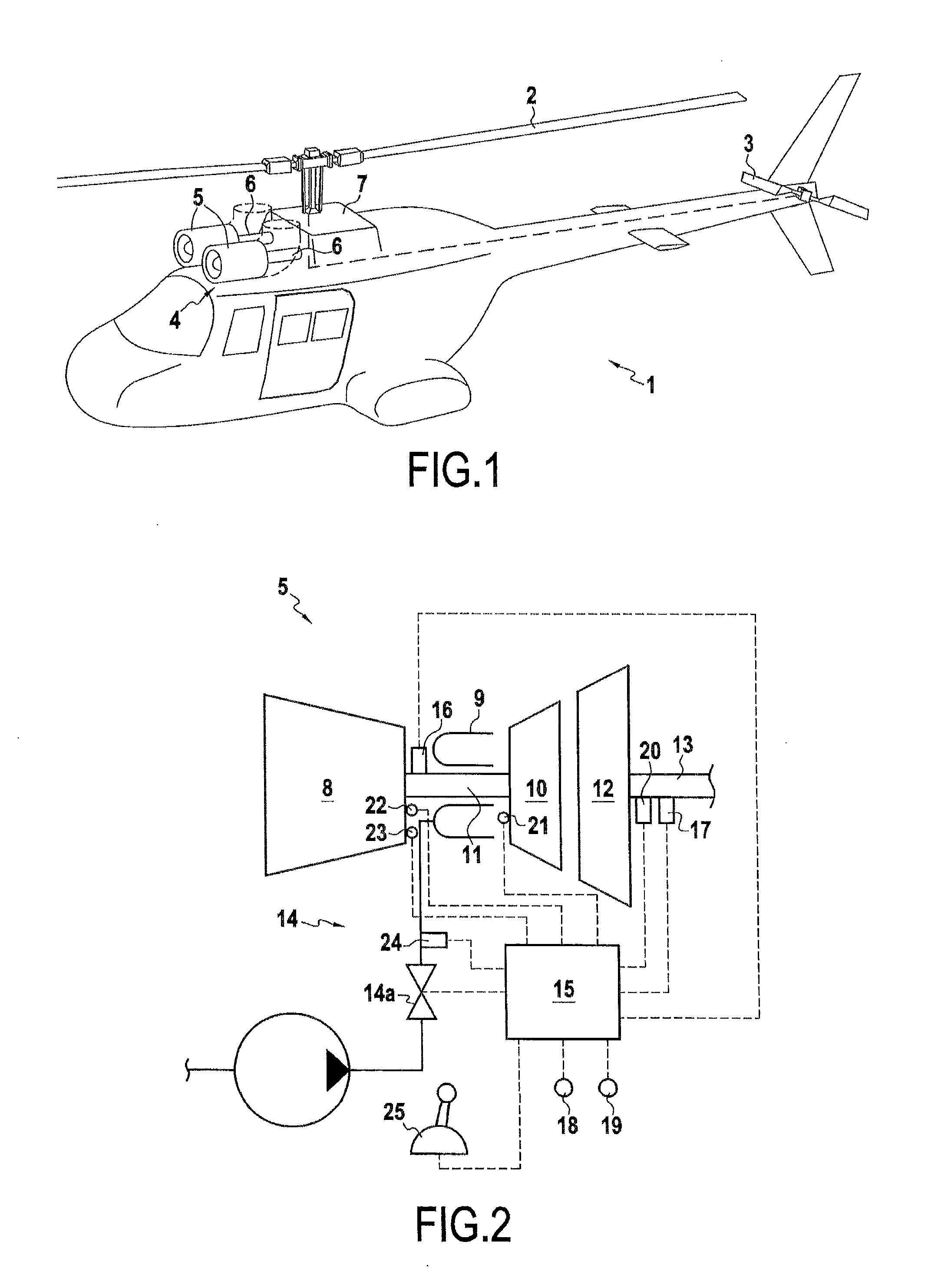
[0023]The first figure shows a rotary wing aircraft 1, more specifically a helicopter having a main rotor 2 and an antitorque tail rotor 3 that are coupled to a power plant 4 in order to drive them. The power plant 4 shown comprises two turboshaft engines 5. More specifically, these engines 5 are turboshaft engines, each having a power takeoff shaft 6 connected to a main transmission gearbox 7 for driving the main rotor 2 and the tail rotor 3.

[0024]One of the engines 5 of the power plant 4 is shown in greater detail in FIG. 2. Each engine 5 comprises a compressor 8, a combustion chamber 9, a first turbine 10 connected by a first rotary shaft 11 to the compressor 8, and a second turbine 12, known as a “free” turbine, that is coupled to a second rotary shaft 13 that is coupled in turn to the power takeoff shaft 6. The assembly formed by the compressor 8, the combustion chamber 9, the first turbine 10, and the rotary shaft 11 is also known as a “gas generator”. A feed circuit 14 serves...


PUM


Abstract

A turbine engine includes a compressor, a combustion chamber, first and second turbines downstream from the combustion chamber, a first rotary shaft constrained to rotate at least with the compressor and the first turbine, a second rotary shaft constrained to rotate with the second turbine, the second rotary shaft nevertheless being free to rotate relative to the first rotary shaft, and a regulator for controlling the feed of fuel to the combustion chamber. The regulator cuts off the feed of fuel to the combustion chamber if the speed of rotation of the second rotary shaft exceeds a maximum threshold that varies as a function of at least one indicative physical parameter associated with mechanical power being extracted from the combustion gas by the second turbine. A method of regulating the turbine engine is also presented.

Description

BACKGROUND OF THE INVENTION[0001]The present invention relates to the field of turbine engines and to regulating them.[0002]The term “turbine engine” is used in the present context to designate any machine for converting heat energy from a working fluid into mechanical energy by expanding said working fluid in a turbine. More particularly, the working fluid may be a combustion gas resulting from a combustion chemical reaction with air in a combustion chamber, after the air has been compressed in a compressor that is driven by the turbine via a first rotary shaft. Thus, turbine engines, as understood in the present context, comprise bypass or non-bypass turbojets, turboprops, turboshaft engines, and gas turbines, amongst others. In the description below, the terms “upstream” and “downstream” are defined relative to the normal flow direction of the working fluid through such a turbine engine.[0003]In particular, the description relates to methods of regulating turbine engines that com...

Claims


Application Information

Patent Timeline
IPC IPC(8): F01D21/02F02C9/46F02C3/10
CPCF01D21/02F02C3/10F02C9/46F05D2270/80F05D2270/021F05D2270/09F05D2220/329F05D2270/091Y02T50/60F02C7/28
Inventor LANGFORD, STEPHENLESCHER, FABIEN
Owner SAFRAN HELICOPTER ENGINES
Why Eureka
Try Eureka