Valve control apparatus

a valve and control apparatus technology, applied in the direction of valve details, valve arrangements, valve drives, etc., can solve the problems of difficult to achieve with a narrow valve included angle, and achieve the effect of reducing mechanical friction, reducing rocker length, and high maximum speed capability

Inactive Publication Date: 2006-12-12
MENDLER EDWARD CHARLES
View PDF12 Cites 17 Cited by
  • Summary
  • Abstract
  • Description
  • Claims
  • Application Information

AI Technical Summary

Benefits of technology

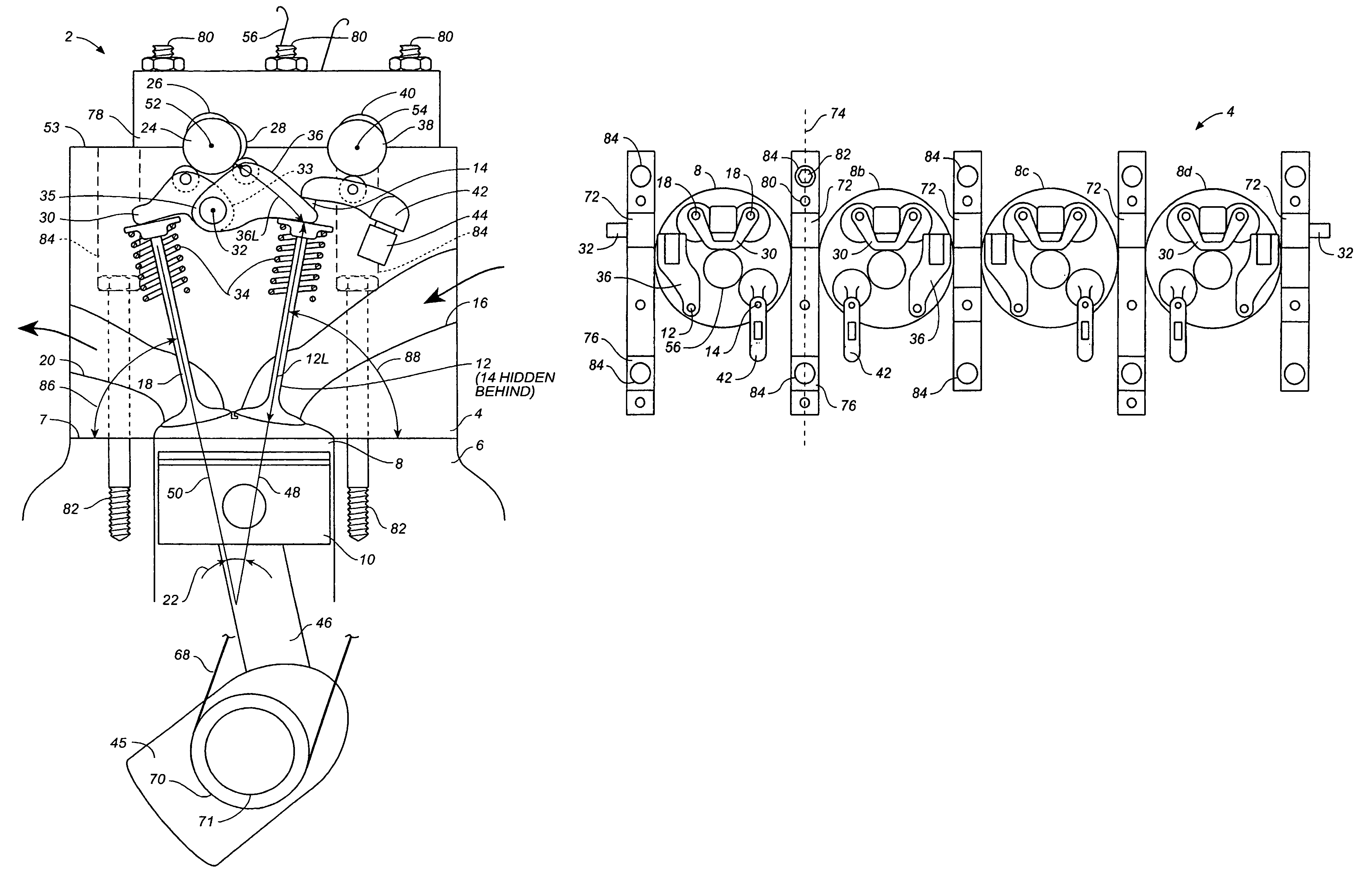
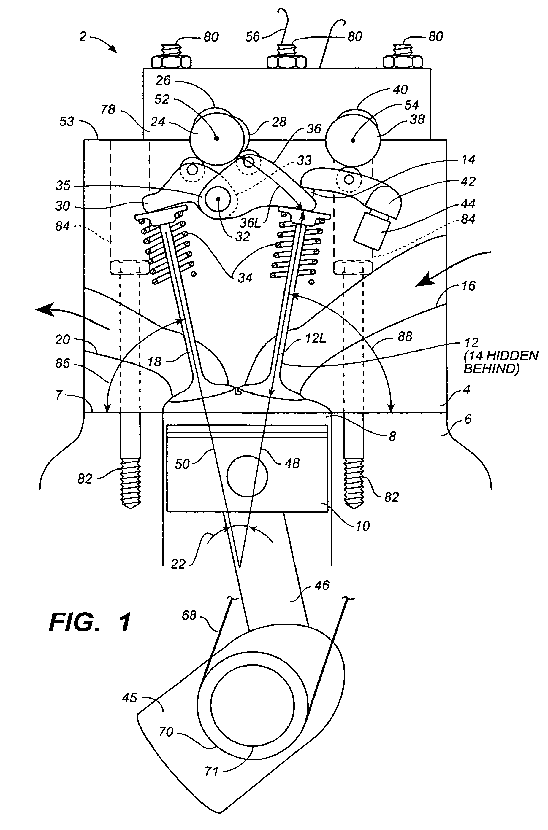
[0010]According to the present invention, air flow into and out of an engine is controlled by two intake valves and one or more exhaust valves per cylinder, the timing of the two intake valves being phase shifted to control the amount of air trapped in the cylinder. A first camshaft operates the exhaust valves and one of the intake valves per cylinder, and a second camshaft operates the second intake valve per cylinder. The phase relationship between the first and second camshaft being adjustable by a phase shifter for adjusting the amount of air trapped in the cylinder. According to the present invention, both the first intake valve and the exhaust valves are actuated by rocker arms and a centrally located first camshaft. The individual rocker arms are short and light weight providing low mechanical friction and a high maximum speed capability. The first camshaft is further located above the rockers providing space for the spark tube within a narrow valve included angle. A narrow valve included angle is also used to further minimize rocker length, in order to minimize rocker mass and friction, and maximize top end engine speed capability. According to the preferred embodiment of the present invention, the two exhaust valves are actuated by a single shaft mounted exhaust rocker, and the first intake valve is actuated by a shaft mounted rocker, the intake and exhaust rockers being mounted on the same shaft, the shaft being located generally on the piston side of the first camshaft, providing a very compact package, and also permitting use of a narrow valve included angle and short rockers. The present invention provides phase shifting between adjacent intake valves for near elimination of throttling and aerodynamic pumping losses, and also provides a high maximum operational speed and generous space for streamlined intake and exhaust ports, permitting high engine power levels to be attained. The present invention is also compact and can be packaged into a broad range of automobile makes and models.
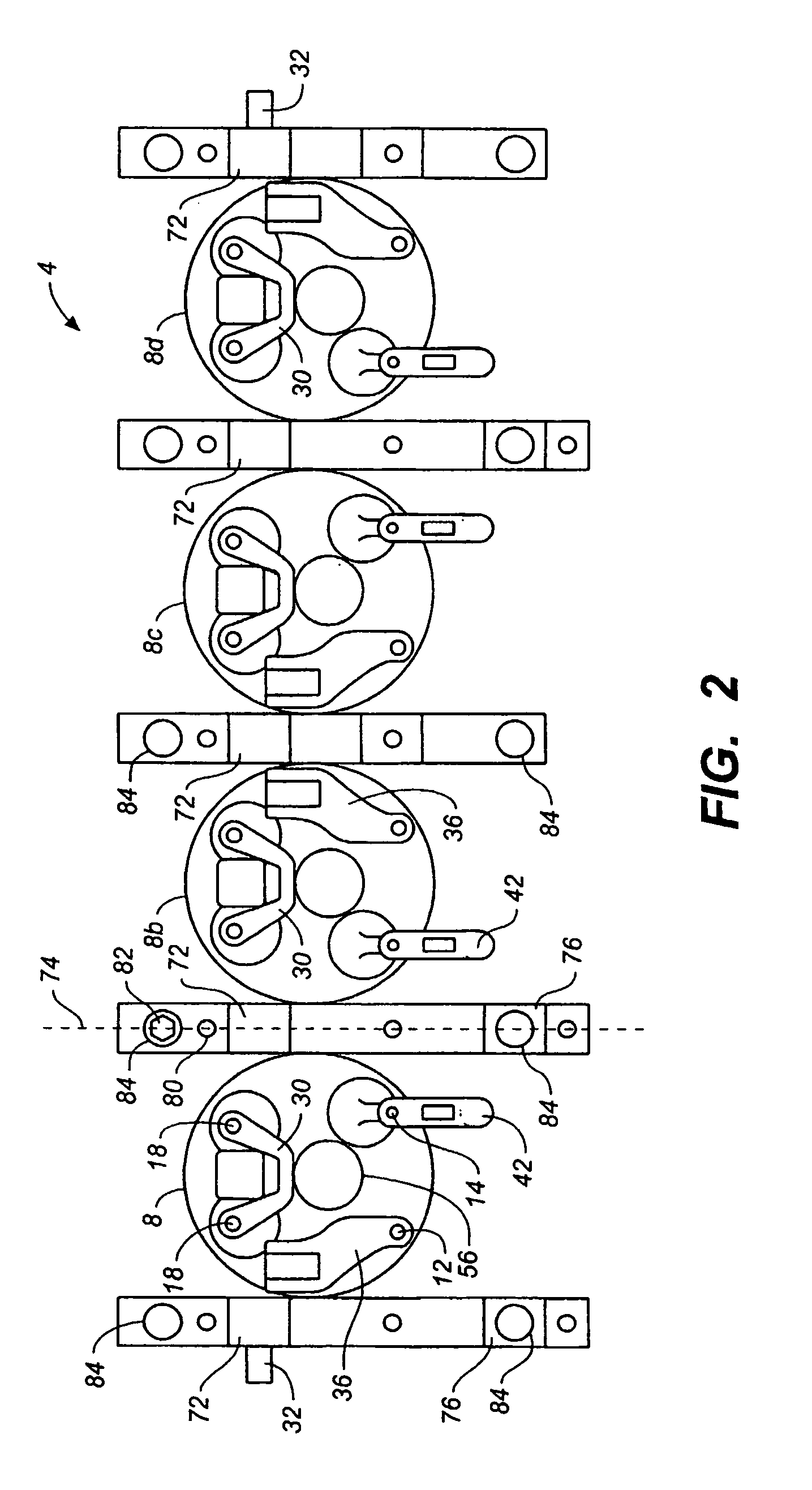
[0011]According to the preferred embodiment of the present invention, the camshaft bearings are located between the cylinders, thereby providing space within the cylinder head for both intake and exhaust rocker arms, and for providing rigid support of the first camshaft with a minimum number of bearings. In the preferred embodiment of the present invention, a cam bearing is located between each pair of adjacent first intake valve rockers for rigid support of the camshaft in general, and the first intake valve cam lobes in particular. Preferably, a single rocker shaft slides into a hole in the cylinder head for rigidly supporting all of the rockers associated with the first camshaft. The present invention is durable and requires no more frequent servicing than current production engines having shaft mounted rockers due to the rigid support and precise alignment of the camshafts and rockers, and due to the short and light-weight intake and exhaust rockers.
[0012]According to the present invention, the axis of rotation of the first camshaft is located between the intake and exhaust valves and the cylinder head bolt tool path axis passes free and clear of the first camshaft bearings, the first camshaft bearings being located approximately on the same axial plain as the cylinder head fastener assembly axis, thereby providing a compact and light weight cylinder head further having undisturbed first camshaft bearings. According to another embodiment of the present invention, the cylinder head bolts may be studs, where the middle bolt head secures the cylinder head to the engine block, and the outer threads are used to secure the cam bearing caps to the cylinder head, thereby providing a compact and light weight cylinder head.
[0013]The present invention provides light-weight rocker arms capable of operating at high engine speeds, and with low attendant friction levels. The present invention does not compromise system life or service requirements, and of significant importance the present invention has the same service requirements as modern production engines having shaft-mounted valve rockers. The present invention provides robust bearing support for the camshafts, and the first camshaft bearings are free and clear of the cylinder head bolts. Additionally, the present invention permits application of a narrow valve included angle, beneficial for modern high compression ration engines, and for future production variable compression ratio engines. The spark tube provides direct access to the spark plug, of essential importance, and difficult to achieve with a narrow valve included angle. A very significant benefit of the present invention is that of low cost. The cylinder head parts for the valve control apparatus of the present invention are inexpensive to manufacture, and the parts can be assembled into the cylinder head at low cost. The present invention provides a high engine performance and low friction levels, in addition to phase shifting of the two intake valves per cylinder for engine power control with greatly reduced throttling losses.

Problems solved by technology

The spark tube provides direct access to the spark plug, of essential importance, and difficult to achieve with a narrow valve included angle.

Method used


Image

  • Valve control apparatus
  • Valve control apparatus
  • Valve control apparatus

Examples


Embodiment Construction

[0022]FIGS. 1, 2 and 3 are intended to illustrate a portion of a valve control apparatus 2 according to the present invention. Valve control apparatus 2 is mounted in a cylinder head 4, cylinder head 4 being mounted on an engine block or cylinder housing 6 having a deck surface 7, a first cylinder 8 and a piston 10 slidably mounted in cylinder 8 for reciprocating motion. Reciprocating motion of piston 10 defines a piston line of action, piston line of action and deck surface 7 being generally perpendicular in the preferred embodiment of the present invention.

[0023]Cylinder head 4 has a first intake valve 12, a second intake valve 14 and at least one intake port 16 for flow of air or another fluid into cylinder head 4 and into first cylinder 8. Cylinder head 4 further has at least one and preferably two exhaust valves 18 and at least one exhaust port 20 for flow of exhaust or another fluid out of first cylinder 8 and out of cylinder head 4.

[0024]Cylinder head 4 further including one ...


PUM


Abstract

A first camshaft (24) operates the exhaust valves (18) and a first intake valve (12) for each cylinder (8), and a second camshaft (38) operates the second intake valve per cylinder (14), the second camshaft further having a phase adjuster (62) for adjusting the timing of the second camshaft (38) relative to the first camshaft (24). Both the exhaust valves and the first intake valve are actuated by rocker arms (30), (36), for providing a short and light-weight first intake valve rocker (36) having a high maximum operational speed capability and low friction. The first camshaft (24) is located above the rockers, the cam followers are located generally in the middle of the rockers (30), (36), and the rocker mounts (33), (35) are located on the inboard ends of the rockers, providing rockers that have both light-weight and a small pivot angle for providing low valve stem to rocker friction.

Description

PROVISIONAL APPLICATION REFERENCE[0001]This application relates to U.S. Provisional Application No. 60 / 236,149 having a filing date of Sep. 29, 2000.BACKGROUND OF THE INVENTION[0002]The present invention relates to a method and apparatus for controlling valves, and more specifically to a method and apparatus for adjusting the timing of internal combustion engine poppet valves.[0003]It has been known for some time that throttling losses contribute significantly to poor engine efficiency at light power levels. In 1958 the Society of Automotive Engineers (SAE) published “Determination of True Engine Friction,” SAE Trans., Vol. 66, pp. 649–661 which deals with throttling and aerodynamic pumping losses. Throttling losses remain a significant problem with spark-ignition passenger cars, as the throttle remains the principal method of regulating engine power output.[0004]German automobile manufacturer BMW announced that it has developed a spark ignition engine with no throttle, and having p...

Claims


Application Information

Patent Timeline
Patent Type & Authority Patents(United States)
IPC IPC(8): F01L1/18F01L1/053F01L1/26F01L1/34
CPCF01L1/022F01L1/053F01L1/185F01L1/26F01L1/34F01L1/024F01L1/026F01L2001/0537F01L2103/01F01L2105/00F01L2800/00F01L2303/01F01L2305/00
Inventor MENDLER, EDWARD CHARLES
Owner MENDLER EDWARD CHARLES
Why Eureka
Try Eureka