Electric door and window guide rail with magnetic levitation linkage function

A technology of magnetic levitation and guide rail, applied in door/window accessories, power control mechanism, suspension device of wing fan, etc., can solve the problems of guide rail wear and small force, and achieve the effect of low noise, easy maintenance and simple structure

Pending Publication Date: 2019-01-11
区应绍
View PDF0 Cites 4 Cited by
  • Summary
  • Abstract
  • Description
  • Claims
  • Application Information

AI Technical Summary

Problems solved by technology

[0003] In order to solve the above technical problems, the present invention provides a magnetic levitation linkage electric door and window guide rail to solve the problem that the existing automatic guide rail driving device does not exert much force on the fixing parts of the door leaf, and the manual opening and closing of the door leaf fixing parts will cause the guide rail to wear and tear.

Method used


Image

  • Electric door and window guide rail with magnetic levitation linkage function
  • Electric door and window guide rail with magnetic levitation linkage function
  • Electric door and window guide rail with magnetic levitation linkage function

Examples


Embodiment 1

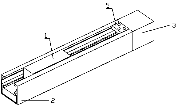
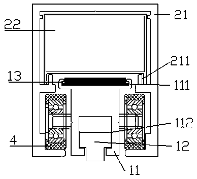
[0027] Embodiment 1: A magnetic levitation linkage electric door and window guide rail.

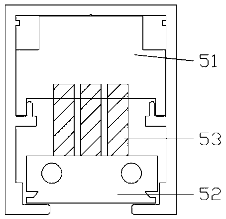
[0028] as attached figure 1 to attach image 3 Shown is a magnetic suspension linkage electric door and window guide rail, which includes a moving block 1, a fixed part 2 that is stationary relative to the moving part, a linear motor drive device 3, a Hall sensor, a plastic-coated bearing pulley 4 and a stopper 5, and the fixed Part 2 includes an outer frame guide rail 21 and a stator core 22 formed by a number of iron core coils arranged in a straight line. The cross-sectional area of ​​the stator core 22 is a rectangle, and the two vertical sides of the rectangle extend out from the bottom and fit in a gap It is arranged in the anti-deformation grooves 211 on both sides of the outer frame guide rail 21. The outer frame guide rail 21 also has empty slots formed by protruding extension sides at the bottom of both sides; Part 12 and several pieces of permanent magnets are arranged in a s...

Embodiment 2

[0034] Embodiment 2: A magnetic levitation guide rail with linkage of double doors and windows.

[0035] as attached Figure 4 to attach Figure 8 A magnetic levitation guide rail with double door and window linkage is shown, which includes a moving block 1 (1a, 1b), a fixed part 2 that is stationary relative to the moving part, a linear motor drive device 3, a Hall sensor, a plastic-coated bearing pulley 4, and a limiter 5 and steel wire rope 6, the fixed part 2 includes an outer frame guide rail 21 and a stator core 22 formed by a number of iron core coils arranged in a straight line, the cross-sectional area of ​​the stator core 22 is a rectangle, and the two vertical sides of the rectangle are The bottom protrudes from the extended side and fits in the anti-deformation grooves 211 arranged on both sides of the outer frame guide rail 21. The length of the stator core 22 is half of the length of the outer frame guide rail 21. The stator core 22 is arranged on the active mov...

Embodiment 3

[0037] Embodiment 3: The application of a double-door-window-linked magnetic levitation guide rail in double-track four-door doors and windows.

[0038] The difference between this embodiment and the second embodiment is that the second embodiment is an application scheme of a single guide rail and double doors. The single guide rail is installed on the wall of the window opening or the door opening, the door and window are opened, and the door and window leaves overlap with the wall; The embodiment is the application scheme of double guide rails and four doors. One of the guide rails in the double guide rails is a common guide rail, and the two doors and windows on both sides are installed on the common guide rails. The two doors and windows in the middle are installed on the magnetic levitation guide rail. The doors and windows on the magnetic levitation guide rail and the doors and windows on the ordinary guide rail are connected by conventional technical schemes. The doors ...


PUM


Abstract

The invention provides an electric door and window guide rail with a magnetic levitation linkage function, and belongs to the field of an electric guide rail for doors and windows. The electric door and window guide rail comprises a motion block, a fixed part, a linear motor driving device, a linkage component and pulleys, wherein the fixed part is resting relatively to a mobile part; the motion block moves in an empty slot of an outer frame guide rail in the fixed part, and the linear motor driving device is arranged on the outer side of the fixed part; the pulleys are fixedly arranged on thetwo sides of the motion block and are in clearance fit to slide in the empty slot of the fixed part; and the linkage component is connected with a driving motion block and a driven motion block of atrack, and thus one motor can drive two doors and windows for linkage moving. The electric door and window guide rail has the advantages of simple structure, easiness in maintenance and high practicality and prevents the fixed part from deforming and linking. Meanwhile, the electric door and window guide rail does not need transmission equipment during electrical moving, so that friction is small,and noise is low.

Description

technical field [0001] The invention belongs to the field of door and window electric guide rails, in particular to a magnetic suspension linkage electric door and window guide rail, and also relates to a magnetic suspension electric door and window guide rail. Background technique [0002] The driving device used in the existing automatic door and window guide rail is a rotating motor as power to drive the movement of the door and window through the transmission of racks or belts. Using magnetic levitation technology combined with PWM (Pulse Width Modu Lation) control technology to realize the control of the moving direction and position of the moving parts in the guide rail. In this design, the fixed parts and moving parts cooperate with each other in the vertical direction to complete the horizontal movement of the moving parts. Movement, the door leaf fixing part can only be fixed by the right angle door leaf fixing part hanger and move with the moving block, but the doo...

Claims


Application Information

Patent Timeline
Patent Type & Authority Applications(China)
IPC IPC(8): E05D15/06E05D13/00E05F15/641
CPCE05D15/0621E05D13/00E05D2015/0695E05F15/641
Inventor 区应绍
Owner 区应绍
Why Eureka
Try Eureka