Energy Converting System

a technology of energy conversion system and conversion system, which is applied in the direction of electric generator control, greenhouse gas reduction, renewable energy generation, etc., can solve the problems of inability to meet the demand of electric power supply, the strength of wind power, and the efficiency of vertical-axis turbines and horizontal-axis turbines, so as to achieve low mechanical friction

Inactive Publication Date: 2012-03-01
LYNN KUO YUAN
View PDF6 Cites 6 Cited by
  • Summary
  • Abstract
  • Description
  • Claims
  • Application Information

AI Technical Summary

Benefits of technology

[0007]Therefore, the object of the present invention is to provide an energy converting system that convert wind and solar energy into electricity with a relative low mechanical friction and, in the mean time, filter out CO2 and impurities in air.

Problems solved by technology

The efficiencies of vertical-axis turbines and horizontal-axis turbines are both limited by strength of wind power.
Thus, conventional wind turbines suffer from the shortcoming that the supply of electric power is unable to meet the demand.
Moreover, since the horizontal-axis turbine station has a huge volume that occupies a relatively wide area, it is typically built in a place remote from a city, thus increasing transmission loss and building cost.

Method used


Image

  • Energy Converting System
  • Energy Converting System
  • Energy Converting System

Examples


Embodiment Construction

[0026]Before the present invention is described in greater detail, it should be noted that like elements are denoted by the same reference numerals throughout the disclosure.

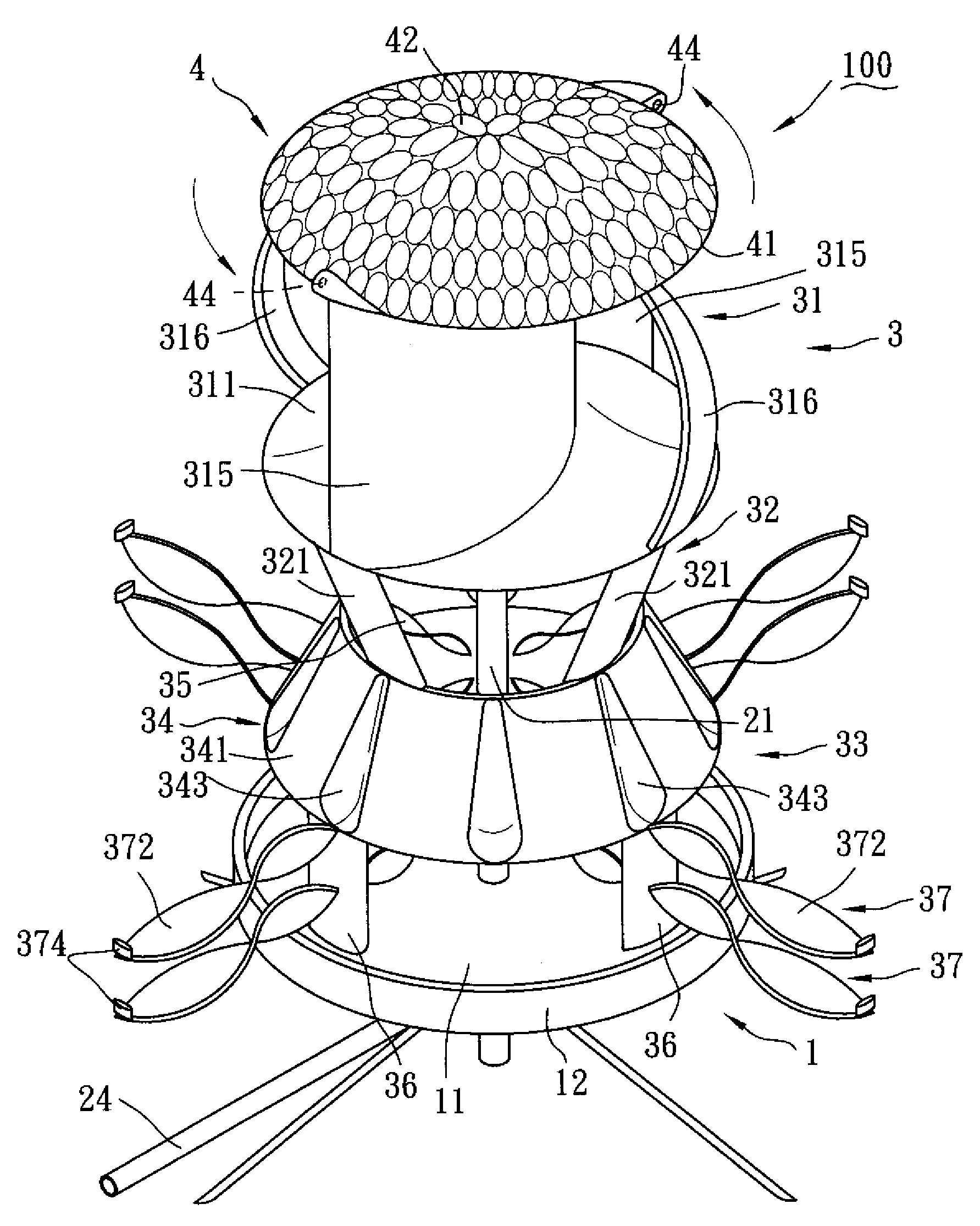
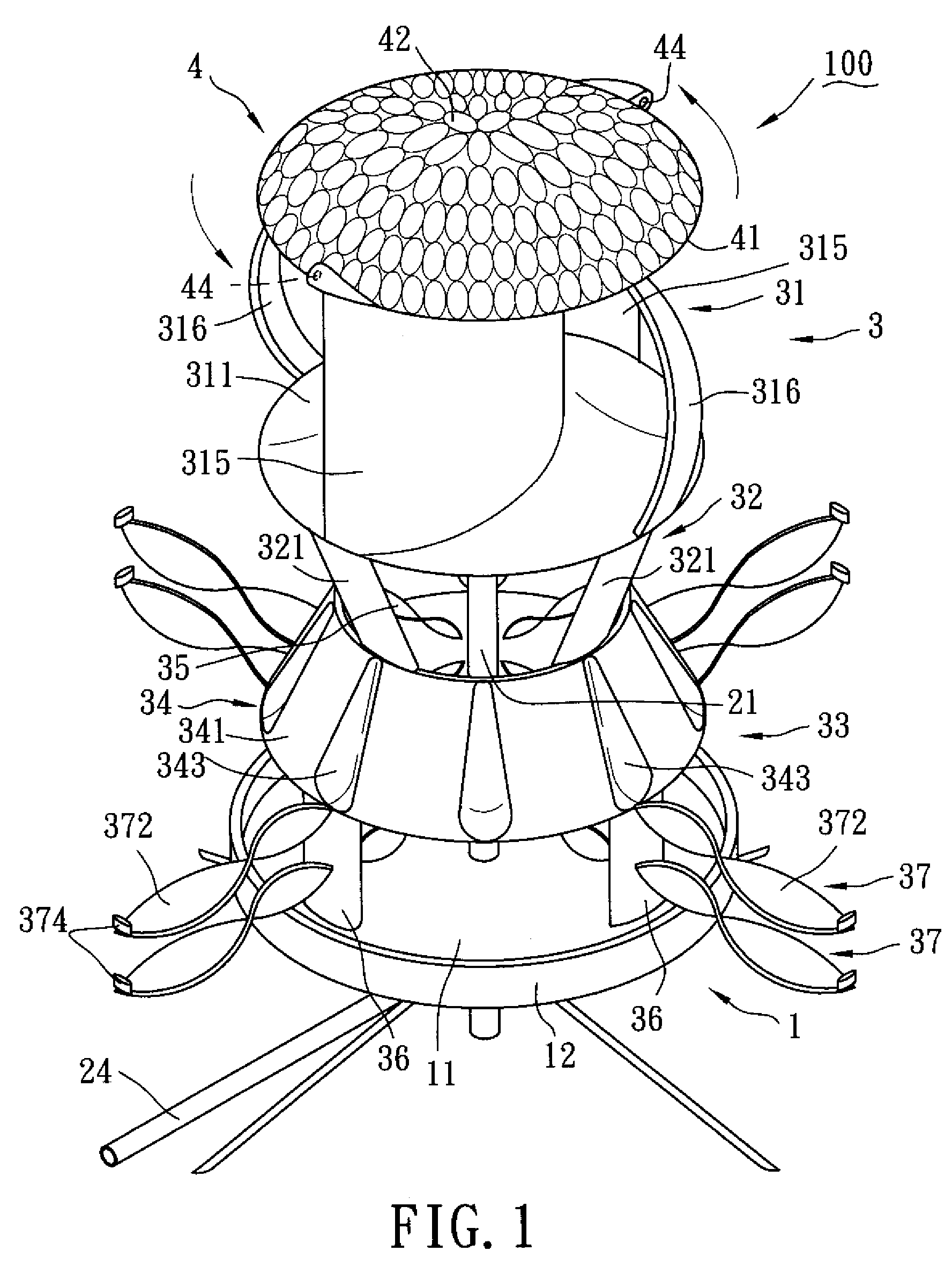
[0027]A first preferred embodiment of an energy converting system according to the present invention is shown in FIGS. 1 to 3. The energy converting system comprises an energy converting mechanism 100 including a base seat 1, a fixed shaft unit 2, a windmill device 3, a light-focusing device 4, a generator 5, and a purifying device 6.

[0028]The base seat 1 includes a main seat body 11, and a magnetized annular flange 12 extending upwardly from a periphery of the main seat body 11 and constituting a top end of the base seat 1.

[0029]Further referring to FIG. 4, the fixed shaft unit 2 includes an upright fixed shaft 21, a plurality of fixed blades 22, a sprayer 23, and a delivery pipe 24.

[0030]The windmill device 3 includes a first windmill unit 31, a second windmill unit 32, and a third windmill unit 33. The first ...


PUM


Abstract

An energy converting system for converting wind energy into kinetic energy has at least one energy converting mechanism that includes a fixed shaft unit including an upright fixed shaft, a windmill device, an air compartment, and a purifying device. The windmill device includes a windmill unit disposed rotatably around the fixed shaft and including at least two first blades driven by the wind energy. The air compartment is disposed above the windmill device. Rotation of the first blades of the windmill unit results in upward flow of compressed air into the air compartment to thereby allow the solar-heated air to be jetted out of the air compartment in such a manner to rotate the windmill device about the fixed shaft. The purifying device is disposed in the air compartment for filtering out impurities in air before the air flows out of the air compartment.

Description

BACKGROUND OF THE INVENTION[0001]1. Field of the Invention[0002]The invention relates to an energy converting system, more particularly to an energy converting system capable of converting solar energy and wind energy into kinetic energy and filtering out impurities in air.[0003]2. Description of the Related Art[0004]Conventional wind turbines are classified into two categories, namely, horizontal-axis turbines and vertical-axis turbines. The efficiencies of vertical-axis turbines and horizontal-axis turbines are both limited by strength of wind power. Thus, conventional wind turbines suffer from the shortcoming that the supply of electric power is unable to meet the demand.[0005]Moreover, since the horizontal-axis turbine station has a huge volume that occupies a relatively wide area, it is typically built in a place remote from a city, thus increasing transmission loss and building cost. Although the vertical-axis turbine has a smaller volume than that of the horizontal-axis turbi...

Claims


Application Information

Patent Timeline
Patent Type & Authority Applications(United States)
IPC IPC(8): F03D9/00
CPCF03D3/005F03D9/007Y02E10/74F05B2220/64F05B2220/00
Inventor LYNN, KUO-YUAN
Owner LYNN KUO YUAN
Why Eureka
Try Eureka