Shaftless type submersible axial flow electric pump

A technology of axial flow electric and submersible motors, applied in axial flow pumps, non-variable pumps, non-displacement pumps, etc., can solve the problems of reduced pump efficiency, impeller stuck, increased hydraulic loss, etc., to eliminate burning The effect of increasing the flow rate of the machine, increasing the water flow, and increasing the operating speed

Pending Publication Date: 2020-11-13
薛峰
View PDF0 Cites 5 Cited by
  • Summary
  • Abstract
  • Description
  • Claims
  • Application Information

AI Technical Summary

Problems solved by technology

[0005] The purpose of the present invention is to provide a shaftless submersible axial-flow electric pump, which solves the problem that the impeller of the current submersible electric pump is fixed by the shaft extension end. When the water flow passes, the impeller shaft and the impeller hub block the high-speed flowing water, resulting in increased hydraulic loss. The efficiency of the water pump is reduced, and when long fibers in the water pass through the impeller, it is easy to wind the impeller and get stuck

Method used


Image

  • Shaftless type submersible axial flow electric pump
  • Shaftless type submersible axial flow electric pump
  • Shaftless type submersible axial flow electric pump

Examples


Embodiment 1

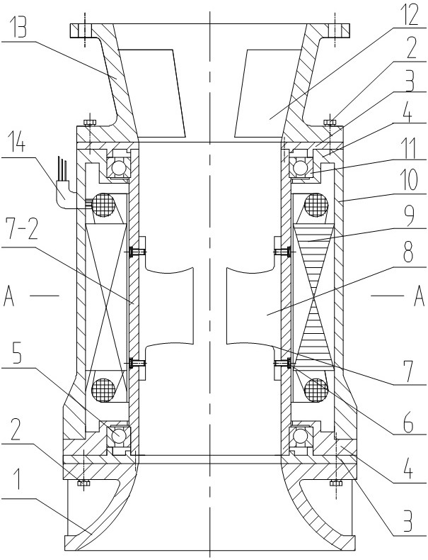
[0035] Example 1: figure 1 Shown is a diagram of a shaftless submersible axial flow pump.

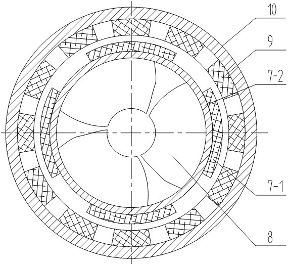
[0036] figure 2 Shown is a schematic diagram of the cross-sectional structure of the shaftless submersible axial flow pump A--A.

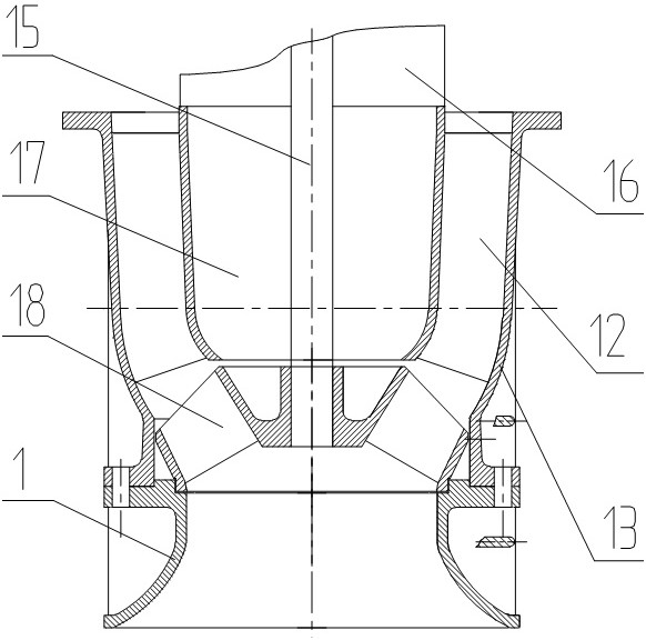
[0037] The water inlet section 1 is located at the bottom of the submersible electric pump and is designed in the shape of a bell mouth to guide the water flow into the inner cavity of the submersible electric pump. , the bearing support seat 4 and the machine casing 10 are closely connected together, and similarly, the guide body 13 is closely connected with the bearing sealing device 3, the bearing support seat 4 and the machine casing 10 through the fastening bolts 2 to form an integral Submersible electric pump;

[0038] The stator winding 9 of the submersible motor extends out of the submersible pump through the lead-out cable and the cable sealing device 14, the stator winding 9 of the submersible motor is tightly combined with the inner wall of t...

Embodiment 2

[0041] Embodiment 2: The bearing device described is a magnetic-fluid double-suspension support bearing; the rotor assembly 7 is supported on the magnetic-fluid double-suspension support bearing. The body is suspended in the space between the stator and the stator, and the suspended rotor assembly 7 is under the action of the high-speed rotating magnetic field of the stator winding 9, and the water pump blade 8 embedded in the inner cylinder rotates at a high speed together with the rotor bushing 7-2. High-speed rotation reduces the mechanical friction of the rotor and improves the efficiency of the pump.

[0042] Others are the same as in Example 1.


PUM


Abstract

The invention discloses a shaftless type submersible axial flow electric pump and belongs to the technical field of water pumps. The shaftless type submersible axial flow electric pump comprises a water intake section, a submersible motor section and a flow deflector section; the lower end of the submersible motor section is connected with the water intake section through a fastening bolt; the flow deflector section is connected with the upper end of the submersible motor section and comprises a flow deflector and a flow deflecting blade; the flow deflector is a frustum shaped cylinder; the flow deflecting blade integrally cast with the frustum shaped cylinder of the flow deflector is arranged on the inner wall of the frustum shaped cylinder of the flow deflector; and the water intake section at the bottom of the pump is a bellmouth shaped cylinder. The shaftless type submersible axial flow electric pump has the following advantages: the shaftless type submersible axial flow electric pump shortens the overall size of the water pump, increases the passing area of the water flow passing through the cavity of the water pump, increases the water passing flow of the water pump, improvesthe hydraulic efficiency, lowers the noise during the operating process of the water pump, improves the passing capacity of sundries in water, and reduces the probability that a water pump impeller is wound with long fiber or other sundries. A magnetic fluid double suspension block bearing increases and improves the operating speed and operating stability of a motor rotor to improve the performance of the water pump.

Description

technical field [0001] The invention relates to the technical field of water pumps, in particular to a shaftless submersible axial flow electric pump. Background technique [0002] At present, the structure of the axial flow submersible electric pump produced by the enterprise adopts the upper pump type or the lower pump type structure. [0003] image 3 In the electric pump of the pump-down structure, a motor (16) is connected to the upper end of the water pump; the water pump includes: water inlet section (1), guide vanes (12), guide body (13), shaft (15 ), the sealing chamber (17) and the impeller (18); the upper end of the water inlet section (1) is connected with a guide body (13), and there is a shaft (15) in the center of the guide body (13), and the shaft (15) passes through The sealed chamber (17), the impeller (18) is connected to the shaft (15) at the lower end of the sealed chamber (17), and the guide vane (12) integrated with the guide body (13) is arranged on ...

Claims


Application Information

Patent Timeline
Patent Type & Authority Applications(China)
IPC IPC(8): F04D13/08F04D3/00F04D29/18F04D29/54F04D29/048F04D29/66
CPCF04D3/00F04D13/0606F04D13/0633F04D13/064F04D13/0646F04D13/0653F04D13/086F04D29/048F04D29/181F04D29/186F04D29/542F04D29/669
Inventor 梁中海薛峰韩有军
Owner 薛峰
Why Eureka
Try Eureka