
Dish washer

A technology for dishwashers and dish racks, which is applied to the washing machine/washing machine for tableware, parts of the washing machine/rinsing washing machine for tableware, cleaning equipment, etc. Small and other problems, to achieve the effect of strong water flow, less water, and large water flow

Inactive Publication Date: 2015-11-04
QINGDAO HAIER DISHWASHER
View PDF11 Cites 7 Cited by
  • Summary
  • Abstract
  • Description
  • Claims
  • Application Information

AI Technical Summary

Problems solved by technology

[0008] The dishwasher using this method is limited by the pipeline and the booster pump. The water spraying volume is small and the water spraying force is small, resulting in long washing time and poor cleaning effect, especially difficult to clean deep tableware, such as bowls, Pots, etc., not suitable for Chinese household use

Method used


Image

  • Dish washer
  • Dish washer
  • Dish washer

Examples


Embodiment approach 1

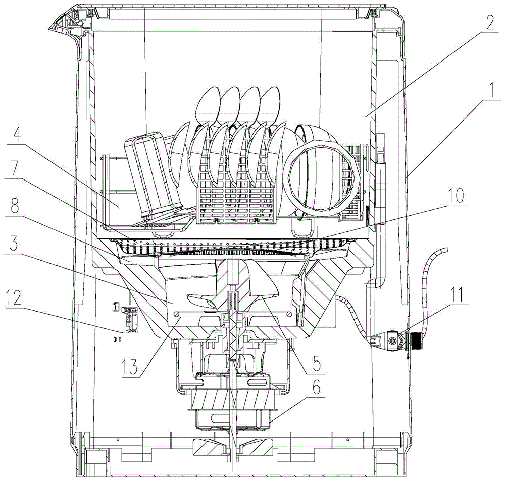
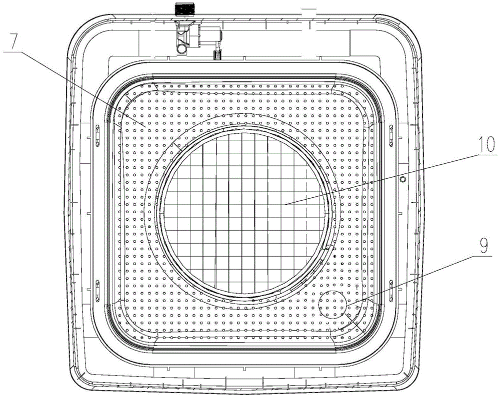
[0031] Such as figure 1 , figure 2 As shown, a dishwasher provided in this embodiment includes a box body 1 and an inner container 2. The box body 1 plays a supporting role for structures such as the inner container 2 arranged inside it. The bottom of the box body 1 is set There is a base, and the upper part is provided with a loam cake.

[0032] The washing of the tableware is all completed in the inner container 2, the bottom of the inner container 2 is provided with a sump 3, and the inner container 2 is provided with a bowl rack 4 for placing the tableware to be cleaned, and the bowl rack 4 is located at the bottom of the sump 3. upper part. A screw propeller 5 is installed in the sump 3 , and the screw propeller 5 rotates under the drive of the driving motor 6 . Specifically, the above-mentioned screw propeller 5 is a pumping paddle, and the pumping paddle includes a rotating shaft and several helical blades arranged on the outer circumference of the rotating shaft. ...

Embodiment approach 2

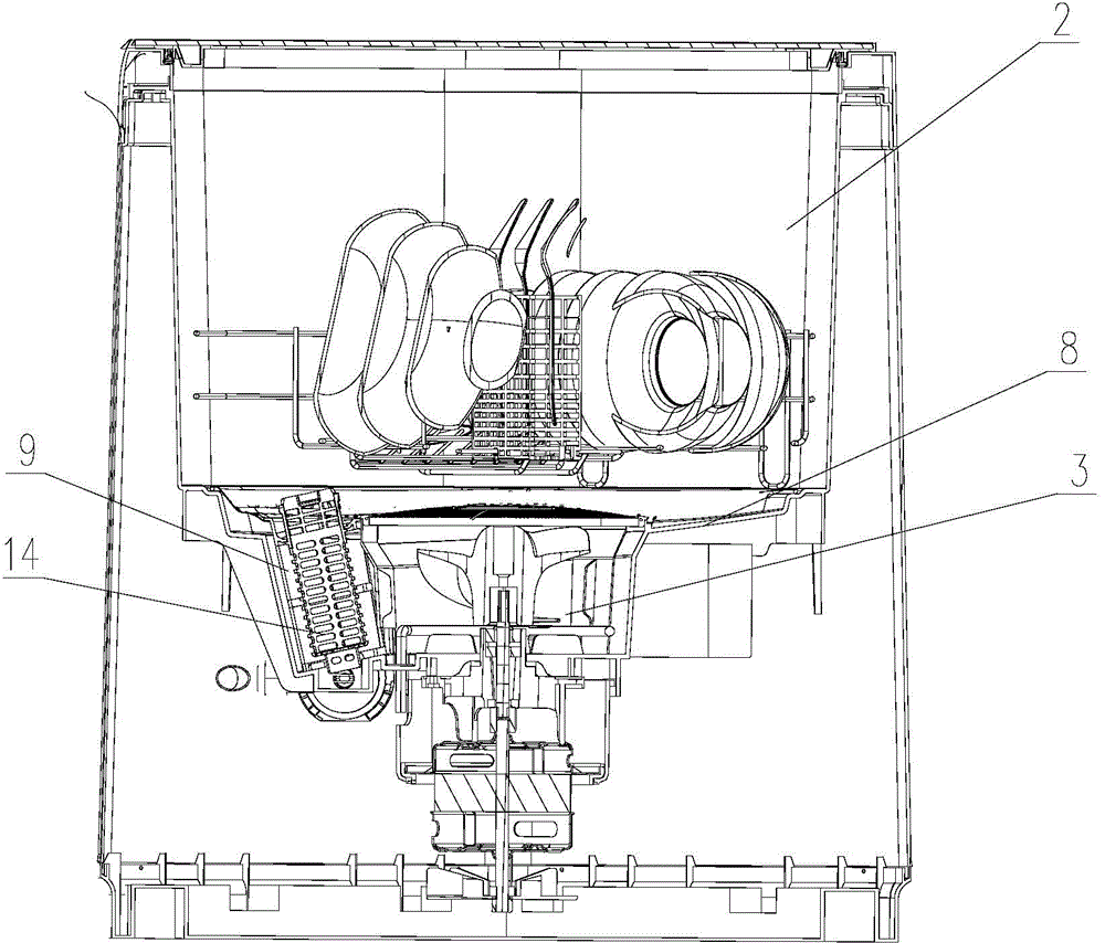
[0041] In this manner, the difference between this embodiment and Embodiment 1 is that the two filter the residue differently. Specifically, such as image 3 , Figure 4 As shown, at least one return channel 9 connecting the sump 3 and the bottom of the liner 2 is provided on the side wall of the sump 3 , and a filter element 14 is disposed in the return channel 9 . More specifically, a circumferential groove 8 is provided at the bottom of the inner tank 2 , and the circumferential groove 8 is arranged along the outer circumference of the sump 3 and communicates with the sump 3 through the return channel 9 with the filter element 14 . Circumferential groove 8 can play the effect of diversion to the cleaning liquid that returns to sump 3, in order to further improve the diversion effect of circumferential groove 8, the bottom of circumferential groove 8 has certain slope, facilitates cleaning liquid to flow into backwater channel 9.

[0042] The specific filtering method for ...


PUM


Abstract

The invention relates to the technical field of household electric appliances used in a kitchen and in particular relates to a dish washer comprising a case body and a liner. The lower part of the liner is provided with a water collection groove; a spiral propeller is disposed in the water collection groove; cleaning liquid in the water collection groove is driven by rotation of the spiral propeller to form high speed projecting water flows, so tableware over the water collection groove can be cleaned; high speed rotation of the spiral propeller enables water flows to be projected out of cleaning liquid surface at high speed in a tapered shape; impact to the tableware surfaces can be achieved; large water flow and great impact as well as strong water flow force are provided; washing time is shortened; great cleaning effect is provided for tableware with great depth; during the washing, the spiral propeller is at least partially arranged in the cleaning liquid, so cleaning liquid can be propelled and form high speed water flow projection and less water amount is required; and the dish washer is simply structured and reliable, possesses great cleaning effect and requires low production cost.

Description

technical field [0001] The invention relates to the technical field of kitchen appliances, in particular to a dishwasher. Background technique [0002] Along with improving day by day of people's living standard, dishwasher more and more enters family as a kind of kitchen appliance product. [0003] At the beginning, dishwashers used a washing principle similar to that of today's wave-wheel washing machines for tableware washing. [0004] As disclosed in the patent document CN2045263U, a scroll-type double-cylinder small tableware washing machine uses the rotation of the pulsator installed at the bottom of the cleaning tank to make the hot water in the tank generate complex turbulent flow, and the tumbling, scouring and friction generated by the water flow The function is to clean the tableware. [0005] Patent document CN2238018Y further proposes a dishwasher, which uses this principle to further improve the structure of the dishwasher. It is equipped with a propeller in ...

Claims


Application Information

Patent Timeline
IPC IPC(8): A47L15/06A47L15/44A47L15/42
Inventor 姜战存蒲杰解婷董媛媛吴玲
Owner QINGDAO HAIER DISHWASHER
Learn More