Hydraulic junction facility

A technology for water conservancy projects and facilities, applied in the field of water conservancy engineering, can solve problems such as the weak combination of earth and rock materials in the dam body, the leakage of the flat culvert pipe under the dam, and the difficulty in rolling around the culvert pipe, etc. Good, low construction requirements

Inactive Publication Date: 2015-10-07
NANCHANG UNIV
View PDF5 Cites 7 Cited by
  • Summary
  • Abstract
  • Description
  • Claims
  • Application Information

AI Technical Summary

Problems solved by technology

However, in the general traditional inclined culvert water intake facilities, the flat culvert pipe under the dam is prone to leakage, the combination with the earth and rock materials of the dam body is not firm, and it is difficult to roll around the culvert pipe, which will cause accidents and endanger the safety of the dam body

Method used


Image

  • Hydraulic junction facility
  • Hydraulic junction facility
  • Hydraulic junction facility

Examples


Embodiment Construction

[0023] In conjunction with the accompanying drawings, the description is as follows:

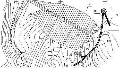
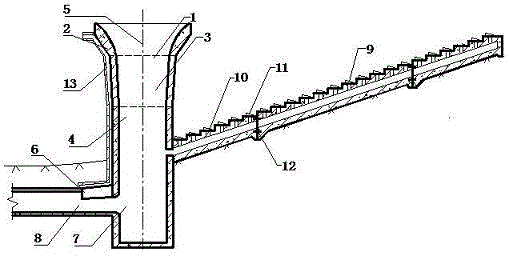
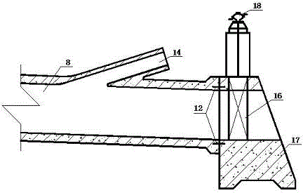
[0024] The water conservancy project facility structure of the present invention includes: vertical shaft spillway (1), bell mouth (2), gradual transition section (3), shaft (4), shaft axis (5), pressure slope section (6), energy dissipation well (7), water retreat tunnel (8), water intake culvert (9), water inlet (10), flap door (11), rubber waterstop (12), ventilation pipe (13), water diversion branch hole (14) , irrigation channels (15), gates at the exit of water retreat tunnels (16), gate piers (17), gate hoists (18), bank slope bedrock (19), earth-rock dams (20), reservoir area (upstream) (21), river course (downstream) (22).

[0025] exist figure 1 Among them, the new type of water conservancy facility composed of the water intake culvert (9) and the shaft type spillway (1) is located in the reservoir area (upstream) (21). The water retreat tunnel (8) of the new type of water conse...


PUM


Abstract

The invention provides a hydraulic junction facility. The structure of the hydraulic junction facility comprises a vertical well type spillway, a horn mouth, a transition segment, a vertical well, an axial line of the vertical well, a pressing slope segment, an energy dissipation well, an annealing tunnel, water taking inclined culverts, water inlets, flap valves, rubber water-stop belts, a breather pipe, a water diversion branch hole, irrigation channels, an annealing tunnel outlet gate, a gate pier, a gate hoist, bank slope bed rocks, an earth and rockfill dam, a reservoir area (the upstream) and riverways (the downstream). In the low water level, inclined lying culvert pipes are utilized to carried out water taking, energy dissipation and water conveying are achieved by utilizing the vertical well type spillway, the annealing tunnel outlet gate is closed to raise a waterhead, the irrigation elevation is increased, and the water using requirement in the downstream is met. The inclined lying culvert pipes are connected with the vertical well type spillway, the vertical well type spillway is utilized to replace a culvert pipe arranged on the lower portion of a dam, and the adverse influence on the culvert pipe arranged on the lower portion of the dam is avoided.

Description

technical field [0001] The invention relates to a water conservancy project facility integrating an oblique culvert pipe and a shaft type spillway, and belongs to the field of water conservancy engineering. Background technique [0002] At present, the well-known reclining culvert pipe water intake water conservancy facility is an irrigation water intake device used in small and medium-sized reservoirs, and it is mainly composed of three parts: a reclining culvert pipe, an energy dissipation pool, and a flat culvert under the dam. The facility draws water through the oblique culvert laid on the reservoir bank slope or the upstream surface of the dam body. The water flowing into the oblique culvert dissipates energy in the rectangular energy dissipation pool at the end of the culvert, and then passes through the flat bottom of the earth-rock dam body of the reservoir. The horizontal culvert pipe is transported downstream. However, in the general traditional oblique culvert w...

Claims


Application Information

Patent Timeline
Patent Type & Authority Applications(China)
IPC IPC(8): E02B8/00E02B8/06
Inventor 魏博文陈春华徐镇凯袁冬阳谷明晗
Owner NANCHANG UNIV
Why Eureka
Try Eureka