Cooling structure of internal combustion engine

a technology for internal combustion engines and cooling structures, which is applied in the direction of machines/engines, mechanical equipment, cylinders, etc., can solve the problems of insufficient water flow rate to the water jacket of the cylinder block on the exhaust side of the internal combustion engine, and achieve the effect of large cooling water flow ra

Active Publication Date: 2012-05-08
TOYOTA JIDOSHA KK +2
View PDF9 Cites 8 Cited by
  • Summary
  • Abstract
  • Description
  • Claims
  • Application Information

AI Technical Summary

Benefits of technology

[0014]The invention provides a cooling structure of an internal combustion engine that may ensure a desirably large cooling water flow rate supplied to the water jacket of the cylinder block on the exhaust side of the internal combustion engine.
[0016]With the cooling structure of an internal combustion engine according to the above-described aspect, the flow of cooling water supplied to the cylinder head side is regulated by the first regulation portion. Therefore, it is possible to ensure a large cooling water flow rate to the portion of the water jacket of the cylinder block on the exhaust side of the internal combustion engine may be ensured. As a result, a state in which the cooling water flow rate to the portion of the water jacket of the cylinder block on the exhaust side of the internal combustion engine is insufficient may be avoided and cooling capability of the portion of the cylinder bore wall on the exhaust side (in particular, the upper portion in the vicinity of the combustion chamber) may be increased.
[0017]In accordance with the invention, because the flow of cooling water supplied to the cylinder head side is regulated by the regulation portion, it is possible to ensure a large cooling water flow rate to the portion of the water jacket of the cylinder block on the exhaust side of the internal combustion engine. As a result, a state in which the cooling water flow rate to the water jacket of the cylinder block on the exhaust side of the internal combustion engine is insufficient may be avoided and cooling capability of the portion of the cylinder bore wall on the exhaust side may be increased.

Problems solved by technology

As a result, a state in which the cooling water flow rate to the portion of the water jacket of the cylinder block on the exhaust side of the internal combustion engine is insufficient may be avoided and cooling capability of the portion of the cylinder bore wall on the exhaust side (in particular, the upper portion in the vicinity of the combustion chamber) may be increased.
As a result, a state in which the cooling water flow rate to the water jacket of the cylinder block on the exhaust side of the internal combustion engine is insufficient may be avoided and cooling capability of the portion of the cylinder bore wall on the exhaust side may be increased.

Method used


Image

  • Cooling structure of internal combustion engine
  • Cooling structure of internal combustion engine
  • Cooling structure of internal combustion engine

Examples


Embodiment Construction

[0028]Embodiments of the invention will be described below with reference to the appended drawings.

[0029]In the below-described embodiment an example will be explained in which the cooling structure of an internal combustion engine in accordance with the invention is applied to a linear four-cylinder internal combustion engine, but the invention may be applied to an internal combustion engine of any system and any number of cylinders.

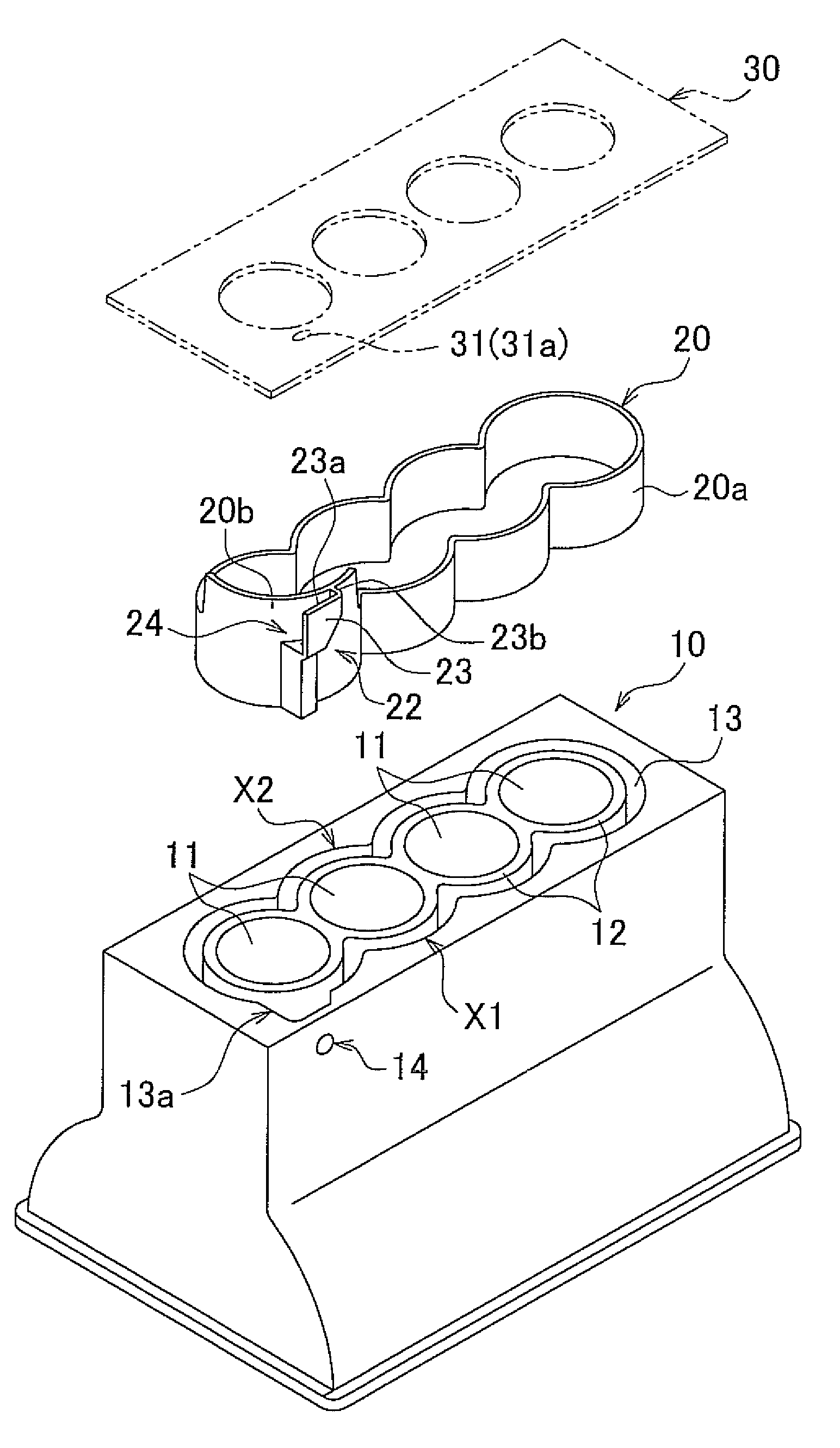
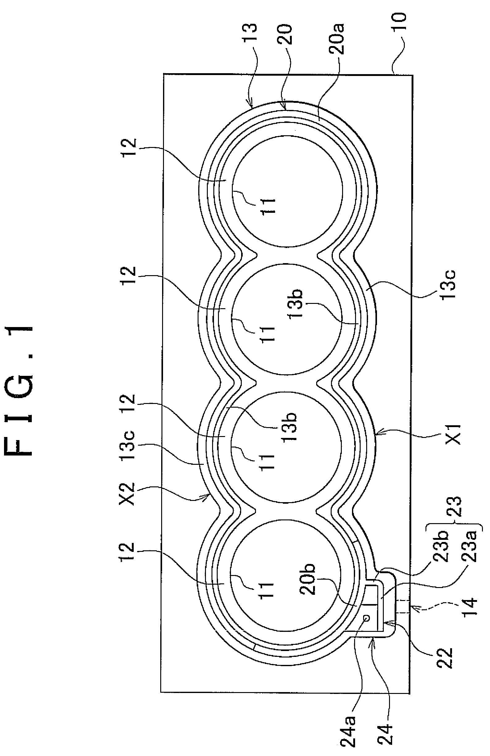
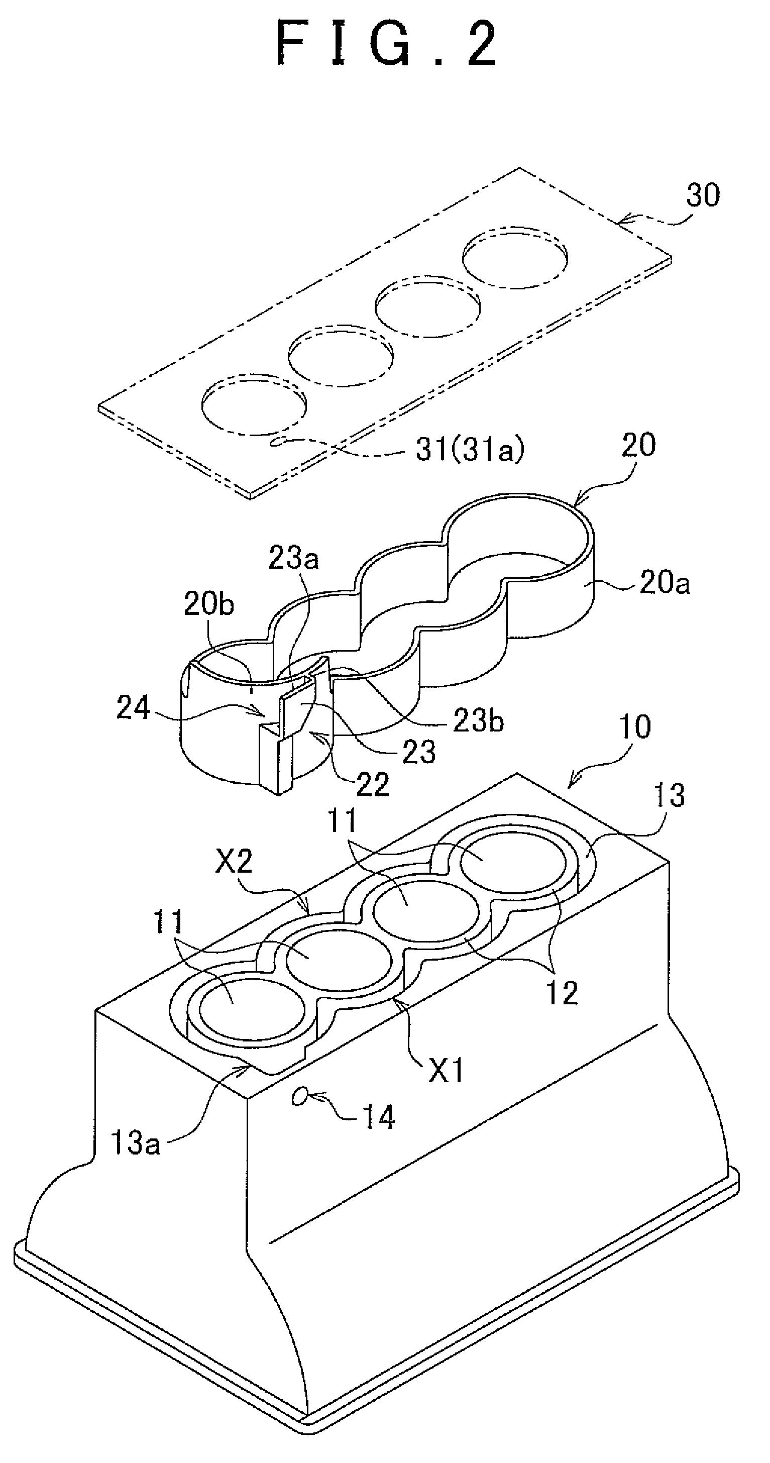
[0030]FIG. 1 is a plan view (a view from a direction perpendicular to a top surface of a water jacket 13) illustrating a schematic configuration of a cylinder block 10 in an internal combustion engine (engine) of the first embodiment. FIG. 2 is a perspective view illustrating the disassembled state the cylinder block 10 and a spacer 20 shown in FIG. 1. FIG. 1 shows an engine cylinder bore 11 of the cylinder block 10 and a peripheral portion thereof and illustrates a disposition state of a cylinder bore row, a water jacket (cooling water passage) 13, and...


PUM


Abstract

A cooling structure of an internal combustion engine includes: a cooling water introducing port provided on one end side of a cylinder block; and a water jacket provided so as to surround a cylinder bore wall, wherein cooling water is introduced from the cooling water introducing port into the water jacket, the cooling water is branched to flow to a portion on an intake side and a portion on an exhaust side of the water jacket of the cylinder block of the internal combustion engine, and the cooling water is supplied from a cylinder block side to a cylinder head side, the cooling structure of the internal combustion engine, further comprising a first regulation portion that regulates a flow of the cooling water supplied to the cylinder head side.

Description

INCORPORATION BY REFERENCE[0001]The disclosure of Japanese Patent Application No. 2008-115933 filed on Apr. 25, 2008 including the specification, drawings and abstract is incorporated herein by reference in its entirety.BACKGROUND OF THE INVENTION[0002]1. Field of the Invention[0003]The invention relates to a structure for cooling an internal combustion engine, for example, of an automobile, with cooling water.[0004]2. Description of the Related Art[0005]In an internal combustion engine, water jackets for causing a flow of a coolant (cooling water) therethrough are provided at a cylinder block side and a cylinder head side. A water jacket of the cylinder block (referred to hereinbelow simply as “water jacket”) is provided so as to surround a cylinder bore wall. In the water jacket, cooling water pumped by a water pump is introduced from a cooling water introducing port formed in a wall portion of the cylinder block. The cooling water introducing port is formed, for example, on one e...

Claims


Application Information

Patent Timeline
Patent Type & Authority Patents(United States)
IPC IPC(8): F02B75/18
CPCF02F1/14F02F1/16F01P2003/021
Inventor HANAI, SHUICHIKUBOTA, TAKASHIHATANO, MAKOTOFUJITA, YOSHIFUMI
Owner TOYOTA JIDOSHA KK
Why Eureka
Try Eureka