High power absorbing waveguide termination for a microwave transmission line

a technology of high-power absorbing waveguides and transmission lines, which is applied in the direction of electric devices, instruments, base element modifications, etc., can solve the problems of failure of the pressure capability of the jacket, the water load of high-power waveguides designed for one frequency may not be suitable for higher frequency applications, and the heating of considerable amounts, etc., to achieve high peak and average power absorbing, easy to construct and assembl

Active Publication Date: 2007-10-16
JOHNSON LIVING TRUST DATED FEBRUARY 14 2006
View PDF8 Cites 7 Cited by
  • Summary
  • Abstract
  • Description
  • Claims
  • Application Information

AI Technical Summary

Benefits of technology

[0015]The temperature rise of the water immediately adjacent to the dielectric jacket, therefore, would be significantly higher at 10 GHz vs 3.0 GHz because of this skin effect, assuming an equivalent heating rate at the interface, because the power is dissipated within a layer that is 1 / 10 the thickness. This means that cooling of the dielectric jacket would be less efficient at the higher frequency.
[0016]The present invention is an improved high power absorbing waveguide termination for a waveguide transmission line which reduces the above described limitations on the power handling capabilities of water loads. The waveguide termination of the invention includes power receiving end that attaches to the waveguide transmission line to be terminated, a waveguide transformer section, suitably a tapered section of waveguide, and an oversize waveguide section terminated by a manifold end block. A dielectric taper extends from the manifold end block into the oversize waveguide section such that the small end of the dielectric taper points toward the waveguide's power receiving end; the taper is additionally inclined with respect to the axis of the oversize waveguide section so as to be laterally displaced, at the tip, to a region of low electric field. The dielectric taper is provided with a fluid circulating passage for circulating fluids throughout the length of the taper from the taper's base to its point end. Fluid circulation within the taper will preferably provide for a substantially complete sweeping of the inside of the taper and for a substantial elimination of air bubbles within the taper. Fluid inlet and outlet passages in the manifold end block communicate with the fluid passage in the taper for conveying fluids into and out of the waveguide taper.
[0017]The waveguide transformer section is of a length and has a cross sectional dependence to transform the input fundamental waveguide size to the oversize waveguide cross section with a minimum of reflection and without excessive coupling to propagating modes other than the fundamental TE10 in the oversize waveguide section. By stepping up to a oversize waveguide section, the heating rate at the tip and elsewhere along the dielectric taper can be reduced significantly compared to what would be experienced in the standard waveguide to be terminated. Also, because of the enlarged waveguide cross section, the tip, length and base of the dielectric taper can become significantly larger as compared to a water load design such as disclosed in U.S. Pat. No. 4,516,088. This permits larger water flow rates without excessive water pressure drops. The larger flow rate allows for larger power dissipation for the same differential temperature change. Moreover, the tip cross section versus the oversize waveguide cross section can be relatively small, thereby reducing r.f. reflection at the tip of the taper, and the surface volume of water next to the taper jacket increased to provide increased power handling capabilities at higher frequencies where the skin effect becomes significant.

Problems solved by technology

Thus, a high power waveguide water load designed for one frequency may be not suitable for higher frequency applications.
The guide size reduction with increasing frequency as well as the frequency term itself can still yield a considerable increase in the heating of the dielectric with a resultant failure of the pressure capability of the jacket.

Method used


Image

  • High power absorbing waveguide termination for a microwave transmission line
  • High power absorbing waveguide termination for a microwave transmission line
  • High power absorbing waveguide termination for a microwave transmission line

Examples


Embodiment Construction

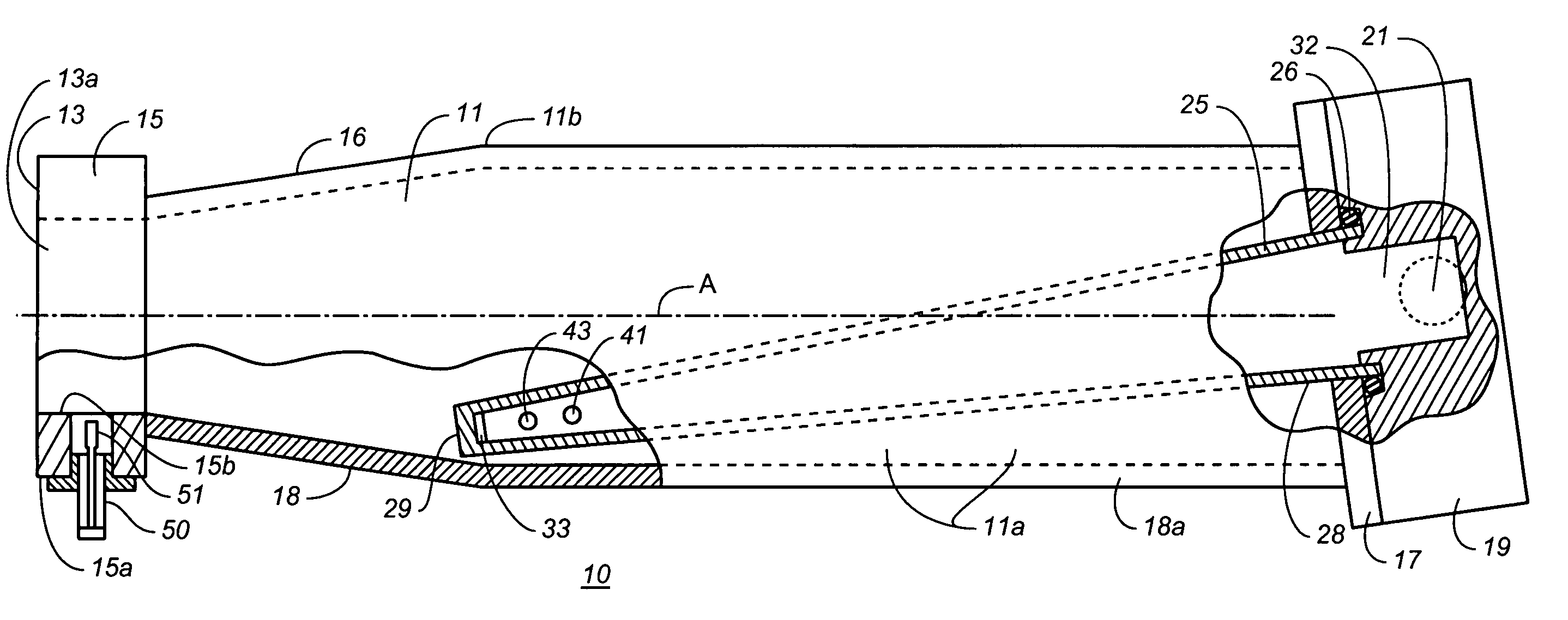
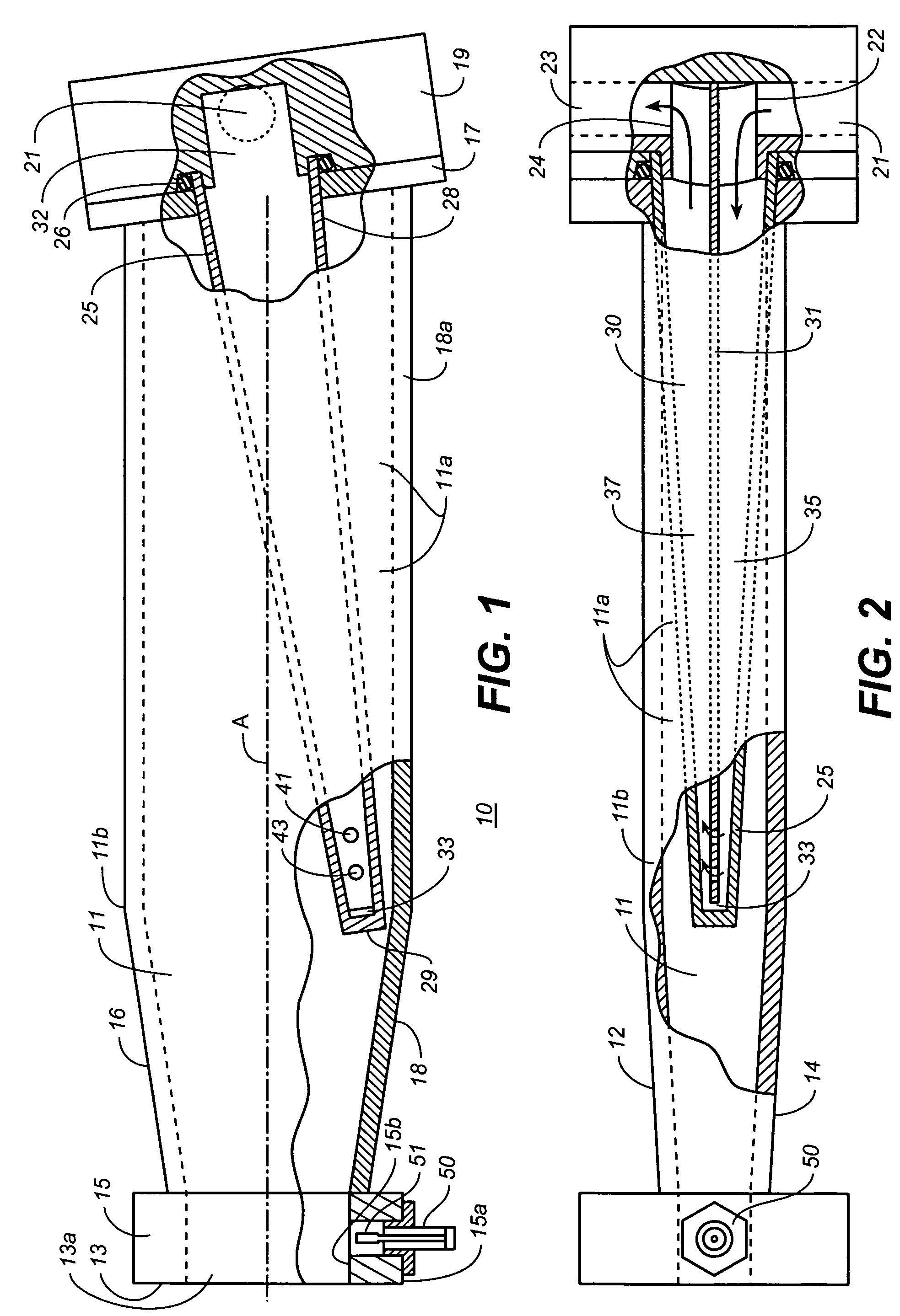
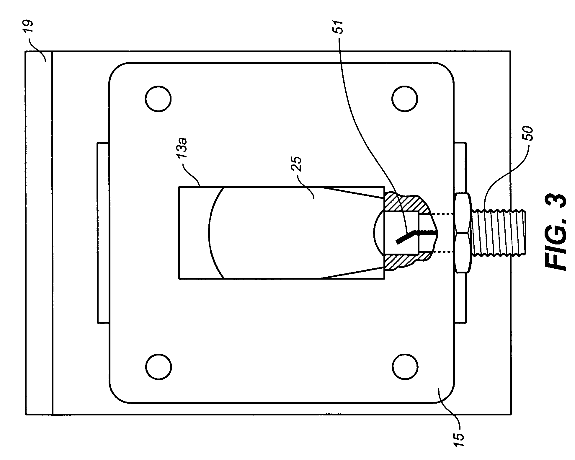
[0026]Referring now to the drawings, FIGS. 1-3 show a power absorbing waveguide termination, generally denoted by the number 10, comprised of a tapered transforming section of rectangular waveguide 11, an oversize waveguide section 11a having back end 17, and a power receiving end 13 having an waveguide input port 13a sized in correspondence with the terminated transmission line waveguide. The waveguide termination 10 attaches to the transmission line to be terminated at its power receiving end by means of a waveguide flange 15. (The illustrated flange 15 is a relatively thick flange for a power monitoring probe as hereinafter described.) The tapered waveguide section, which is disposed between the oversize waveguide section and power receiving end 13, acts to match the input port 13a to oversize waveguide section 11a so that microwave power received by the termination's power is conducted to the oversize waveguide section with minimal power reflection. Because of its increased size...


PUM


Abstract

A high power absorbing waveguide termination for a microwave transmission line has a power receiving end with a waveguide input port, an oversize waveguide section, and a transforming waveguide section for connecting the waveguide input port to the oversize waveguide. A dielectric taper disposed in the oversize waveguide section has a fluid passage therethrough to allow fluid, most suitably water, to sweep the taper and absorb microwave power introduced into the oversized waveguide section. Fluid is suitably fed into and extracted from the dielectric taper via a manifold end block at the back end of the oversize waveguide section. The taper is inclined relative to the center axis of the oversize waveguide section so as to position the point end of the taper in a region of very low electric field strength for the oversize waveguide section's fundamental mode. A power monitoring probe is optionally provided at the input port of the waveguide termination.

Description

CROSS-REFERENCE TO RELATED APPLICATIONS[0001]This application claims the benefit of U.S. provisional application No. 60 / 622,470, filed Oct. 25, 2004.BACKGROUND OF THE INVENTION[0002]The present invention relates to microwave devices generally and more specifically to matched impedance waveguide termination devices used for absorbing high microwave power propagated down a waveguide transmission line.[0003]In high power microwave applications, it is often necessary to terminate a transmission line with a substantially matched load capable of absorbing and dissipating the power transmitted into the load. Methods of terminating a waveguide transmission line have been developed involving solid materials as the power absorbing medium, however, in most cases the absorbing medium is water or a water mixture. Where such fluid is used the general class of termination devices is generically referred to as “water loads”.[0004]In designing a water load it is usually desirable to produce a load w...

Claims


Application Information

Patent Timeline
Patent Type & Authority Patents(United States)
IPC IPC(8): H01P1/26
CPCH01P1/262
Inventor JOHNSON, RAY M.
Owner JOHNSON LIVING TRUST DATED FEBRUARY 14 2006
Why Eureka
Try Eureka