Low Drag Piston

a piston and low drag technology, applied in the direction of pistons, machines/engines, mechanical equipment, etc., can solve the problems of failure to disclose a piston having an inwardly concave central portion with a first and second oil control ring, and achieve the effect of reducing mechanical losses, improving efficiency of reciprocating engines, and reducing friction

Active Publication Date: 2012-09-13
GUNNING ROHAN
View PDF14 Cites 4 Cited by
  • Summary
  • Abstract
  • Description
  • Claims
  • Application Information

AI Technical Summary

Benefits of technology

[0012]In view of the foregoing disadvantages inherent in the known types of low drag pistons now present in the prior art, the present invention provides a new reciprocating en

Problems solved by technology

These prior art devices are well adapted for their particular purpose, but fail to disclose a piston having an

Method used


Image

  • Low Drag Piston
  • Low Drag Piston
  • Low Drag Piston

Examples


Embodiment Construction

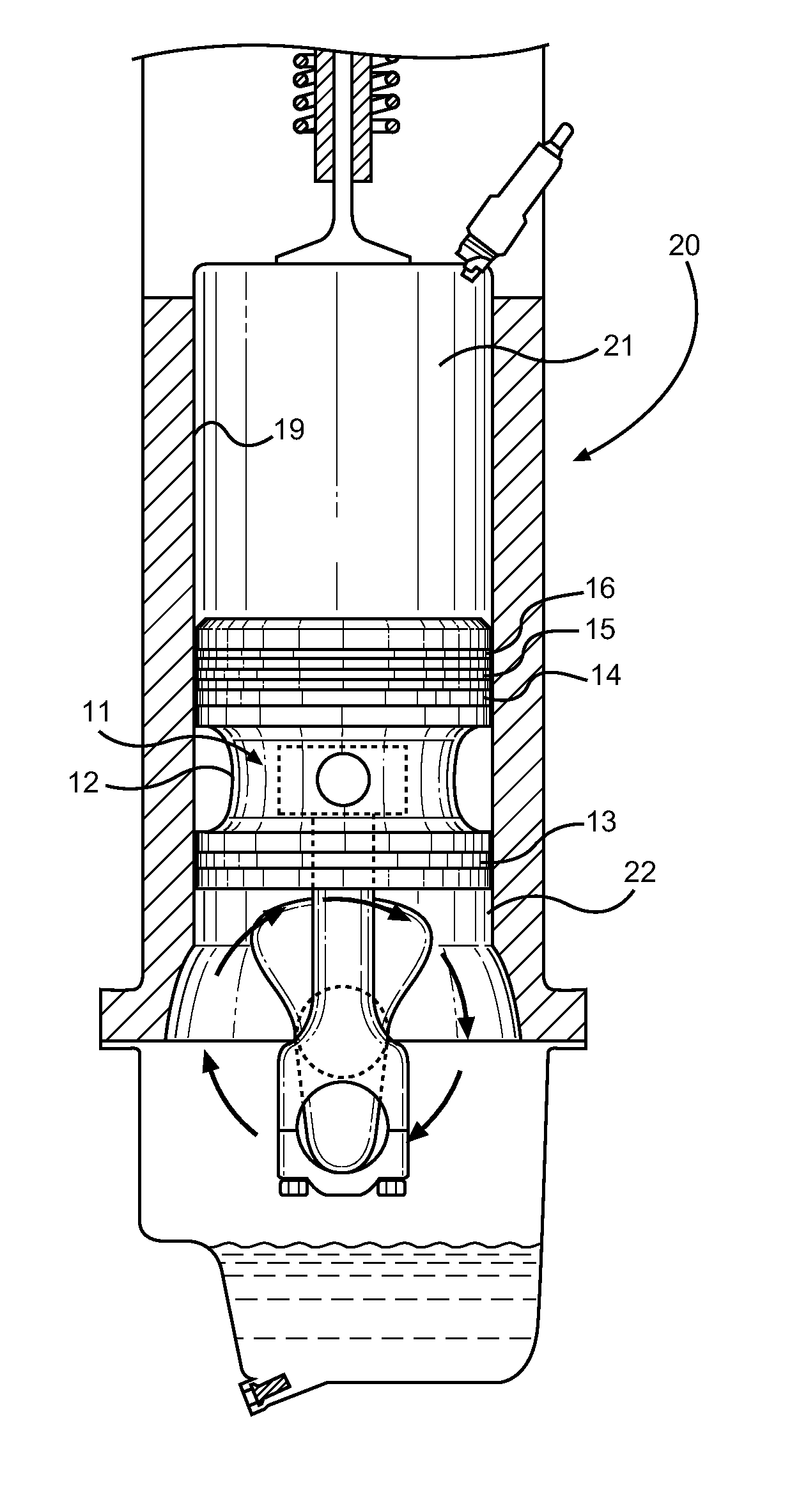
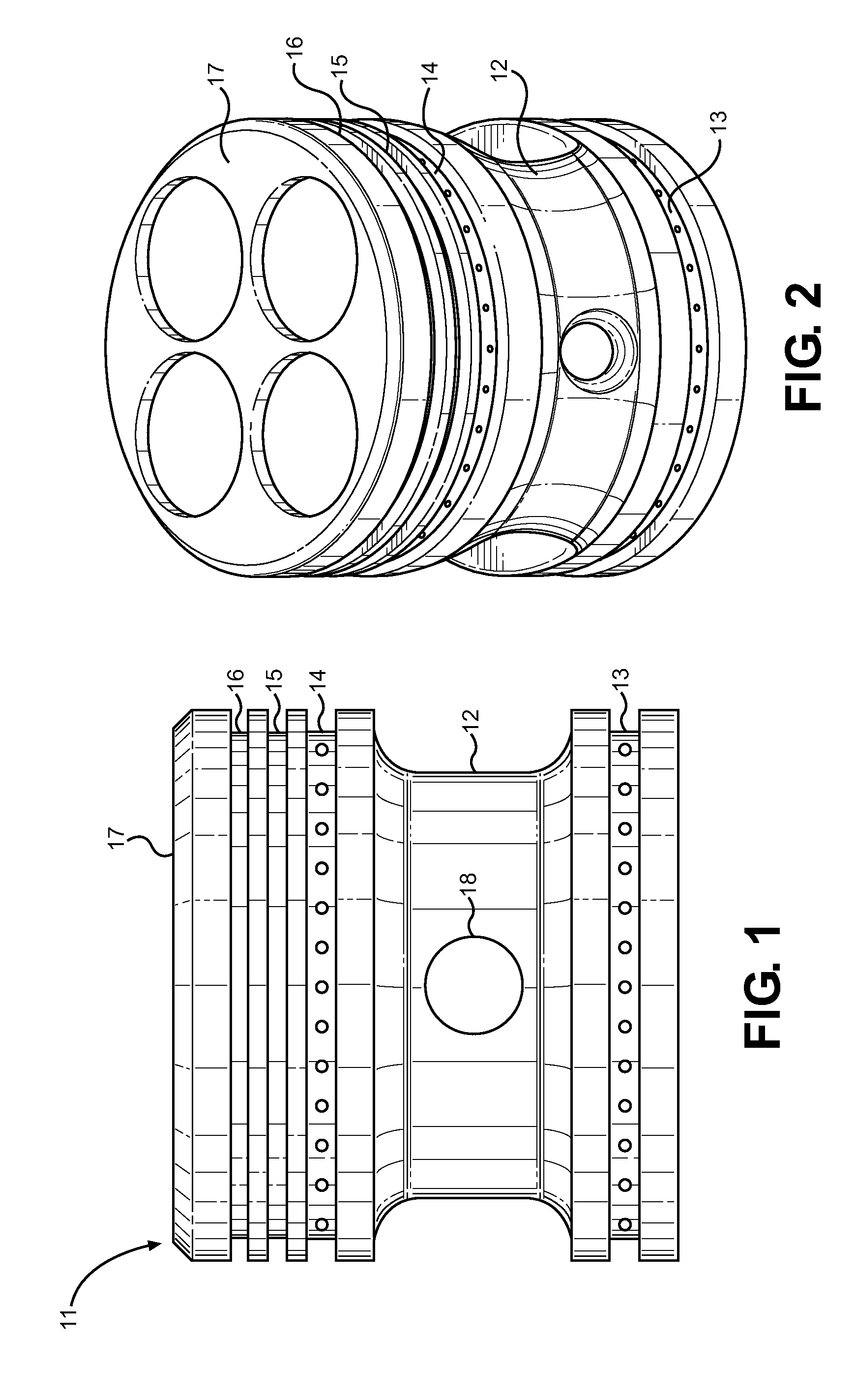
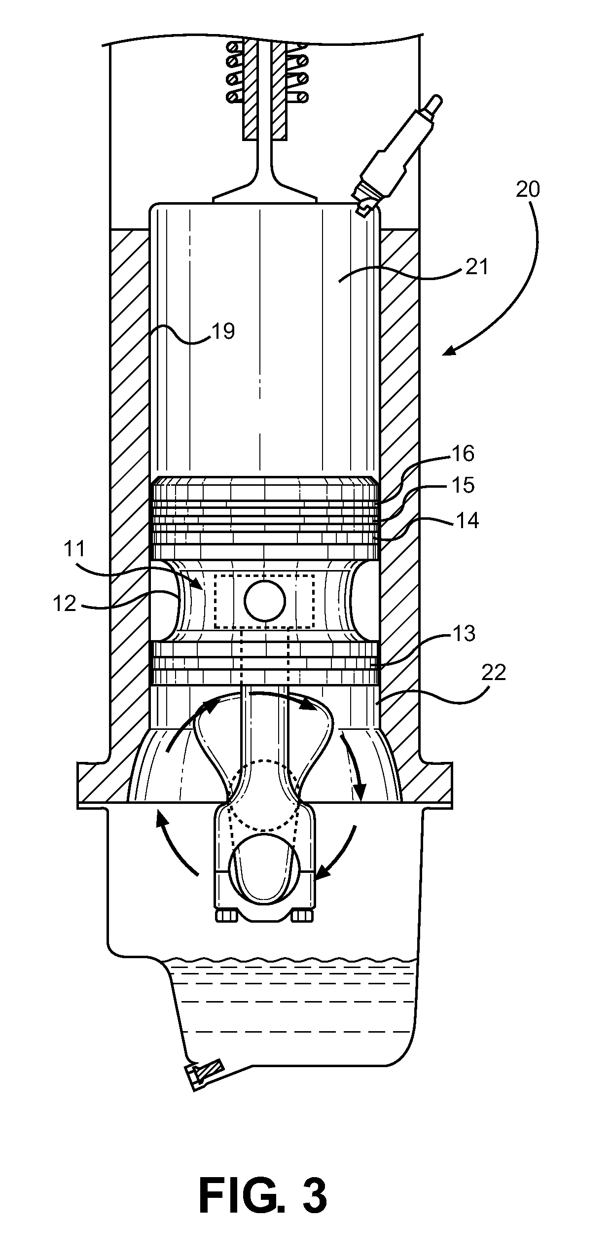
[0024]Reference is made herein to the attached drawings. Like reference numerals are used throughout the drawings to depict like or similar elements of the low drag piston. For the purposes of presenting a brief and clear description of the present invention, the preferred embodiment will be discussed as used for reducing friction, mechanical losses and improving engine efficiency within a reciprocating engine. The figures are intended for representative purposes only and should not be considered to be limiting in any respect.

[0025]Referring now to FIG. 1 through 5, there is shown a view of the low drag piston of the present invention. The piston 11 is a cylindrical device adapted to travel within a reciprocating engine and utilize the power of an expanding fuel-air mixture to turn a crank shaft. Its function is to utilize the expanding gases while sealing the combustion chamber and controlling lubrication along the interface between the piston and the bore of a cylinder. The presen...


PUM


Abstract

Disclosed is a low drag piston for a reciprocating engine that comprises a piston head that reduces mechanical and viscous friction while improving oil lubrication and thermal load dissipation throughout the piston stroke. The piston comprises a cylindrical crown and lower skirt area such that these elements are the only surfaces in contact with the cylinder walls and support a plurality of piston rings, while the interior skirt region is recessed inward in a concave shape to reduce drag, friction and thermal expansion interferences. An additional oil control ring increases oil outflow to further reduce friction and drag, while the pin boss that holds the connection between the piston head and the connecting rods is recessed inward within the inwardly concave central portion.

Description

CROSS REFERENCE TO RELATED APPLICATION[0001]This application claims the benefit of U.S. Provisional Application No. 61 / 450,451 filed on Mar. 8, 2011, entitled “Low Drag Automotive Piston.”BACKGROUND OF THE INVENTION[0002]1. Field of the Invention[0003]The present invention relates to reciprocating engines and piston designs, particularly in the automotive field. More specifically, the present invention pertains to a high efficiency piston that reduces viscous drag and mechanical losses as it translates through its range of motion from bottom dead center (BDC) to top dead center (TDC) within a reciprocating engine.[0004]Reciprocating engines utilize a piston-cylinder configuration to capture the power of expanding gases to create work in the form of translation of the piston within the cylinder, which in turn rotates a crank to power a vehicle, operate an electrical generator or perform a duty unto which rotating mechanical power is a motive input. An engine piston is positioned with...

Claims


Application Information

Patent Timeline
IPC IPC(8): F02F3/00
CPCF02F3/00
Inventor GUNNING, ROHAN
Owner GUNNING ROHAN
Why Eureka
Try Eureka