Bearing structure and turbocharger

a technology of bearing structure and turbocharger, which is applied in the direction of sliding contact bearings, rigid support of bearings, machines/engines, etc., can solve the problem of large influence of viscosity resistance of lubricating oil on mechanical loss, and achieve the effect of reducing mechanical loss

Inactive Publication Date: 2017-02-16
IHI CORP
View PDF9 Cites 5 Cited by
  • Summary
  • Abstract
  • Description
  • Claims
  • Application Information

AI Technical Summary

Benefits of technology

[0014]According to the present invention, it is pos...

Problems solved by technology

Consequently, influence of viscous resistance...

Method used


Image

  • Bearing structure and turbocharger
  • Bearing structure and turbocharger
  • Bearing structure and turbocharger

Examples


Embodiment Construction

[0019]Hereinafter, an embodiment of the present invention will be explained in detail with reference to the attached drawings. Dimensions, materials, concrete numerical values etc. shown in such embodiment are nothing but exemplifications for making understanding of the invention easy, and do not limit the present invention unless otherwise noted in particular. Note that, in the description and drawings, to components having substantially the same function or configuration, the same sign is attached and repeated explanation is omitted, and diagrammatic representation of components having no direct relationship to the present invention is omitted.

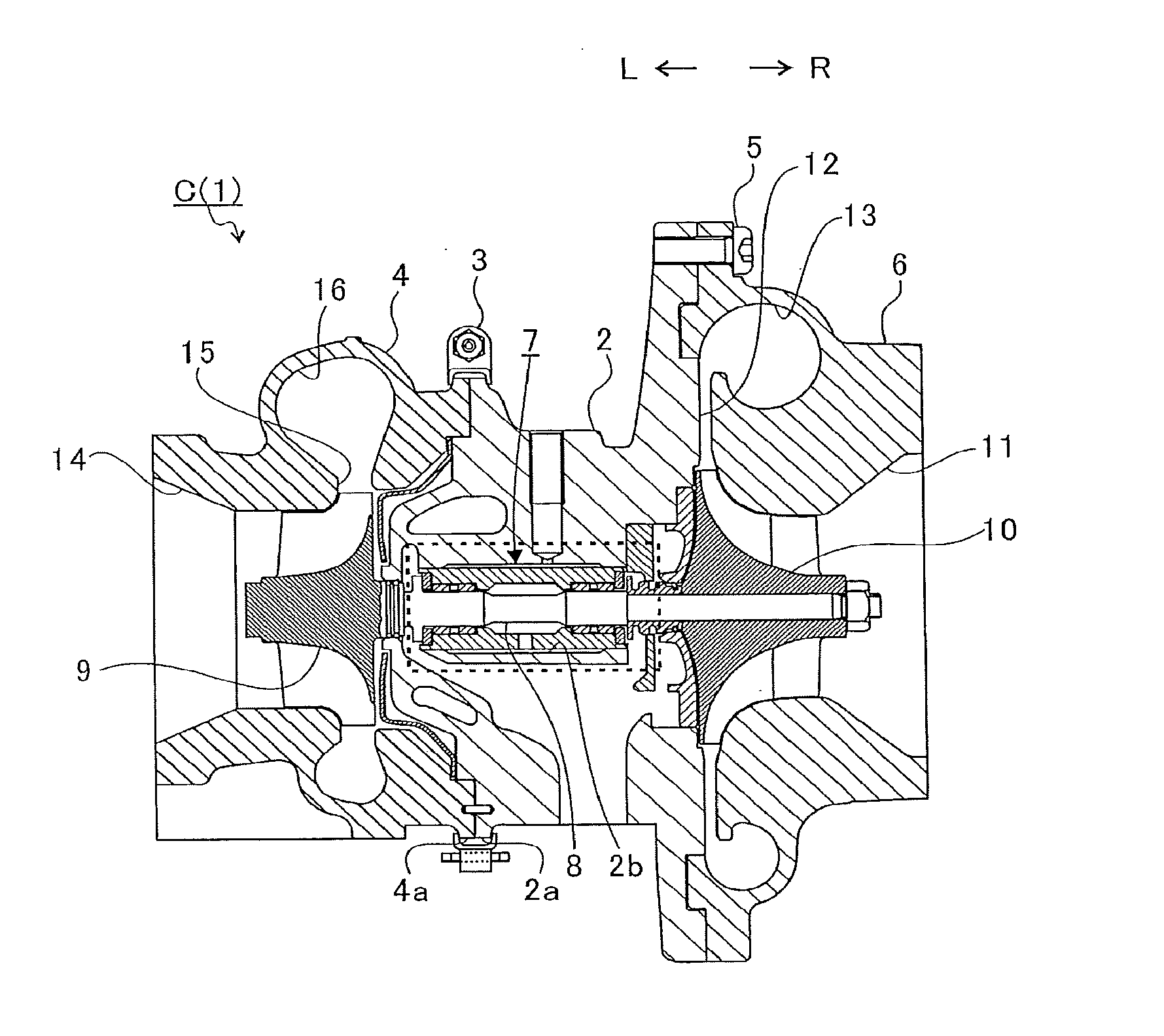
[0020]FIG. 1 is a schematic cross-sectional view of a turbocharger C. In what follows, explanation will be given with a definition that an arrow L shown in FIG. 1 shows the direction of the left side of the turbocharger C, and that an arrow R shows the direction of the right side of the turbocharger C. As shown in FIG. 1, the turbocharger C ...


PUM


Abstract

A bearing structure includes a bearing holder that has a hollow main body and an oil hole penetrating through from an outer circumferential surface to an inner circumferential surface of the main body to thereby guide a lubricating oil to the inside of the main body, and that is fixed in a bearing housing; two full-floating metal bearings that are arranged separated from each other in the axial direction of the shaft and support the shaft, in the bearing holder; two thrust bearing surfaces each arranged on the outside of two full-floating metal bearings in the axial direction of the shaft; and two collars each arranged on the outside of two thrust bearing surfaces in the axial direction of the shaft and provided for the shaft. The lubricating oil lubricates thrust bearing surfaces after lubricating full-floating metal bearings.

Description

CROSS REFERENCE TO RELATED APPLICATIONS[0001]This application is a continuation application of International Application No. PCT / JP2015 / 071068, filed on Jul. 24, 2015, which claims priority to Japanese Patent Application No. 2014-168257, filed on Aug. 21, 2014, the entire contents of which are incorporated by reference herein.BACKGROUND[0002]1. Technical Field[0003]The present invention relates to a bearing structure in which a shaft is supported by a full-floating metal bearing, and to a turbocharger.[0004]2. Description of the Related Art[0005]Heretofore, there is known a turbocharger in which a shaft is supported rotatably by a bearing housing and the shaft is provided with a turbine wheel at one end of the shaft and a compressor wheel at the other end of the shaft. Such turbocharger is connected to an engine, and the turbine wheel is rotated by exhaust gas discharged from the engine, and the compressor wheel is rotated by the rotation of the turbine wheel via the shaft. In this ...

Claims


Application Information

Patent Timeline
IPC IPC(8): F16C33/10F16C35/02F16C17/18F02B39/14F16C17/26
CPCF16C33/1045F02B39/14F16C2360/24F16C17/18F16C35/02F16C17/26F16C17/02
Inventor UNEURA, YUTAKAKANEDA, SHINICHIDAITO, YUICHIKOJIMA, HIDEYUKISUGIURA, TOMOMIBUNNO, KENJI
Owner IHI CORP
Why Eureka
Try Eureka